89
Configuration of Function Blocks Section 3-1
Connecting analog
signals (variables)
and accumulated
value signals
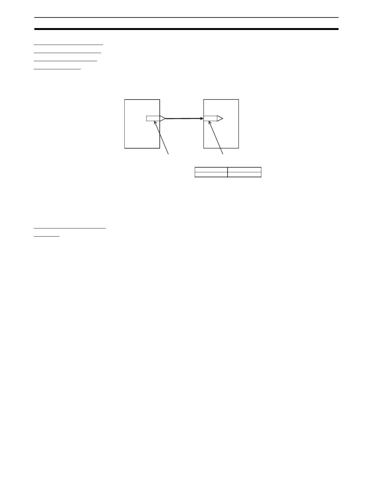
Specify in the analog input ITEMs which analog output ITEM and its block
address are to be used to introduce analog signal function blocks on the input
side.
Example To introduce ITEM006 (PV) of the Basic PID block of block address 001 from
ITEM011 (Y1) of the Square Root block of block address 100.
Note Connection of analog signals or accumulated value signals can be executed
on CX-Process Tool separately from setting of ITEM data as wiring of function
blocks. (Connection of analog signals or accumulated value signals can also
be set as ITEM data.)
Connecting contact
signals
Contact signals are connected via the Sequence Table block (Block Model
302), Step Ladder Program block (Block Model 301), or the Contact Distribu-
tor Block (Block Model 201). *1
Specify both contact inputs (Sequence Table block, Step Ladder Program
block, or Contact Distributor block to specified function block) and contact out-
puts (specified function block to Sequence Table block, Step Ladder Program
block, or Contact Distributor block) in the Step Ladder Program block (Block
Model 301) or the Contact Distributor Block (Block Model 201). Do not specify
these contact signals to ITEMs in the specified function block.
Note On CX-Process Tool, connection of contact signals is executed at setting of
ITEM data.
∗1: As an exception, with some of the ITEMs (PV error input of ITEM018 and
MV error input of ITEM090 of the Basic PID block or the Advanced PID
block) contacts are input specified as the source designation.
011 006
Block address: 100 Block address: 001
Y1
PV
Block address: 001
ITEM number Data
006 100011
Basic PIDSquare Root