94
Description of Operation Section 3-2
!WARNING Always stop the operation of the Loop Controller before converting any of the
EM Area to file memory. If any part of the EM Area that is being used by the
Loop Controller for the HMI is converted to file memory during Board opera-
tion, the system may operate in an unexpected manner, which may result in
injury. Analog Input/Output Units used in combination with the Loop Controller
must be mounted correctly, and the unit number set on the front panel of the
Analog Input/Output Unit must match the unit number set on the Field Termi-
nal block. If the unit numbers do not match, input/output (read/write) is per-
formed on the data of another Special I/O Unit (whose unit number is set on
the Field Terminal block).
!WARNING Be sure to check the status of the connected devices before transferring the
settings for the MV tight shut function and MV analog output inversion function
to the Loop Controller. If the transfer destination is incorrect, unexpected oper-
ation of the machinery and equipment may result.
!WARNING When program pattern data is transferred from the Loop Controller to the CPU
Unit, be sure to confirm that the transfer destination words are not also used
by another Unit. If the transfer destination words are used by another Unit, the
system may operate unexpectedly or hazardously.
!WARNING When program pattern data is transferred from the CPU Unit to the Loop Con-
troller, be sure to confirm that the program pattern data is set correctly. If
incorrect program parameters are transferred to the Loop Controller, the Loop
Controller may operate unexpectedly or hazardously.
Selecting the START mode at power ON
Whether to use a cold start or a hot start when the PLC’s power supply is
turned ON or the Loop Controller is restarted (i.e., when A60800, the Inner
Board Restart Bit, is turned from OFF to ON) can be set by using the CX-Pro-
cess Tool to set ITEM018 (START mode at power ON) in the System Com-
mon block (Block Model 000).
There are four START modes that can be set.
Note Access from the CX-Process Tool software and data exchange be-
tween the Loop Controller and the CPU Unit or other external de-
vices will not be possible at startup until either A609.01 or A609.02
turns ON.
Default mode
The default mode when the PLC’s power supply is turned ON or the Loop
Controller is restarted is a hot start for CS-series PLCs and a hot start within
specified time for CJ-series PLCs. Refer to 3-2-3 Details of Hot Start, Cold
Start and Stop State for details on the start modes.
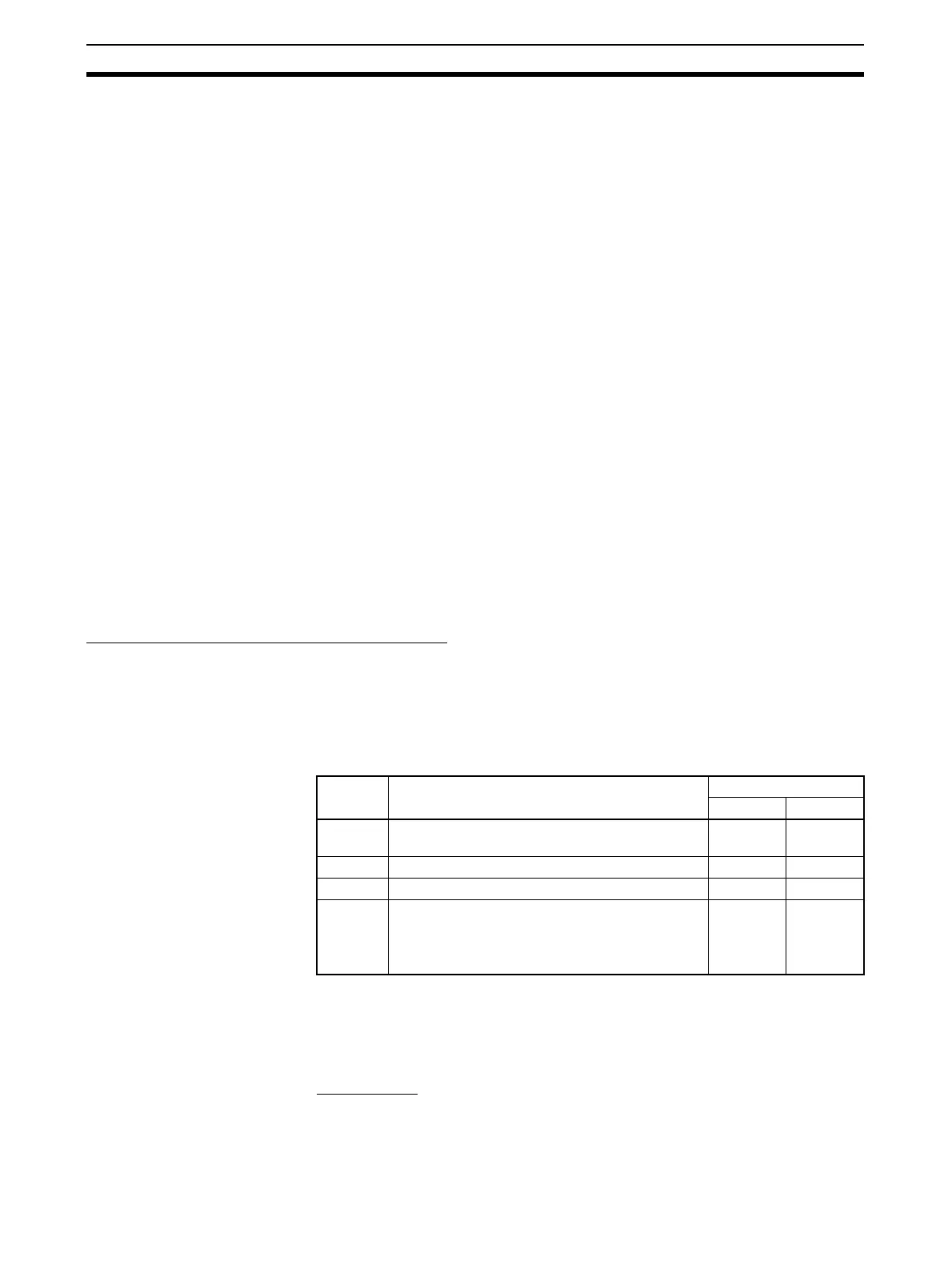
ITEM018 Content Default
CS Series CJ Series
0 Hot start within specified time (supported for
LCB01/05 version 2.0 or later and LCB03).
--- Default
1 Hot start Default ---
2 Cold start --- ---
3 (See
note.)
Specification from CPU Unit (Not supported for
CS1D-LCB05D.)
(A60901 turns ON to indicate a hot start, A60902
to indicate a cold start.)
--- ---