11
Outline Section 1-1
each function block. The MV at stop setting can also be used to specify the
MV when PID calculations are stopped.
Previously, alarm processing and PV input processing was stopped when cal-
culation stopped for each function block. With this function, however, PID cal-
culation only is stopped and the quantity specified for the MV is maintained
while the calculation can be restarted.
Sequence Table
Referencing
Evaluation results of the condition rules for a sequence table can be refer-
enced from another sequence table. This enables common processing (as
with subroutines) to be compiled in a table for referencing.
Step Ladder Timer
Command
A timer can be used in the Step Ladder block (Block Model 301).
User Link Table Pulse
Output
In user link tables, when a specified ITEM in a function block starts, a pulse
(one-shot pulse) that turns ON only for one refresh cycle can be written to the
specified bit address in the CPU Unit’s I/O memory. This enables trigger sig-
nal output processing and other tasks for the CPU Unit to be performed sim-
ply from the Loop Controller.
Expanded User Link
Table EM
Specification
In user link tables, EM bank numbers 1 to C can be specified as the memory
type to enable user link tables to be used even when EM bank number 0 is
being used in ladder programs or file memory functions with functions other
than the Loop Controller.
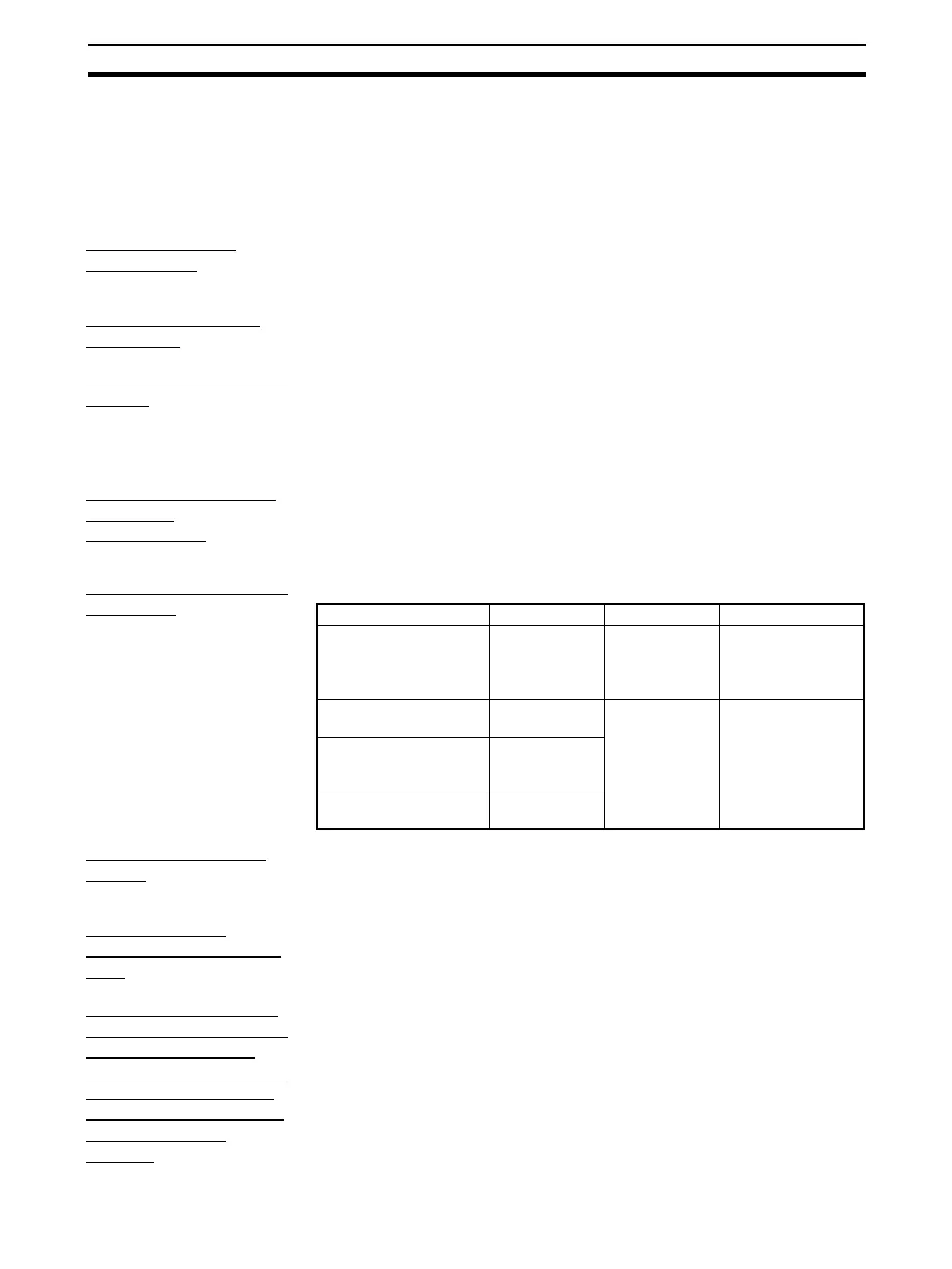
Field Terminal Blocks
Increased
I/O field terminal blocks have been added for the following Units.
Switch Meter Block
Added
The Switch Meter block (Block Model 225) has been added. This block
enables starting/stopping multiple devices such as motors and pumps, and
simple manipulation and monitoring of the status of ON/OFF valves.
Constant ITEM
Setting (Block Model
171)
The number of constants that can be set for the Constant ITEM Setting (Block
Model 171) has been increased from 8 maximum to 16 maximum.
Saving Tag Settings,
Comments, and Block
Diagrams Created
with CX-Process Tool
to the Internal Flash
Memory (CX-Process
Tool Ver. 5.0 or
Higher)
CX-Process Tool Ver. 5.0 or higher enables tag settings, comments, and block
diagram information created using the CX-Process Tool to be backed up in
the Loop Controller’s internal flash memory.
Unit name Model Block Model Block Name
CS-series Analog Input
Unit
CS1W-AD161 582 AI 16-point Terminal
(AD161) CS1W-
AD161
CJ-series Isolated-type
Thermocouple Input Unit
CS1W-PTS15 571 AI 2-point Terminal
(PRS15/16, PDC15)
CJ-series Isolated-type
Resistance Thermome-
ter Input Unit
CJ1W-PTS16
CJ-series Isolated-type
Direct Current Input Unit
CJ1W-PDC15