19
Outline Section 1-1
2. The Loop Controller uses user link tables (regardless of the user program
on the CPU Unit) to read and write to specified CPU Unit I/O memory. So,
do not perform write operations on the same I/O memory addresses be-
tween the Loop Controller and the CPU Unit.
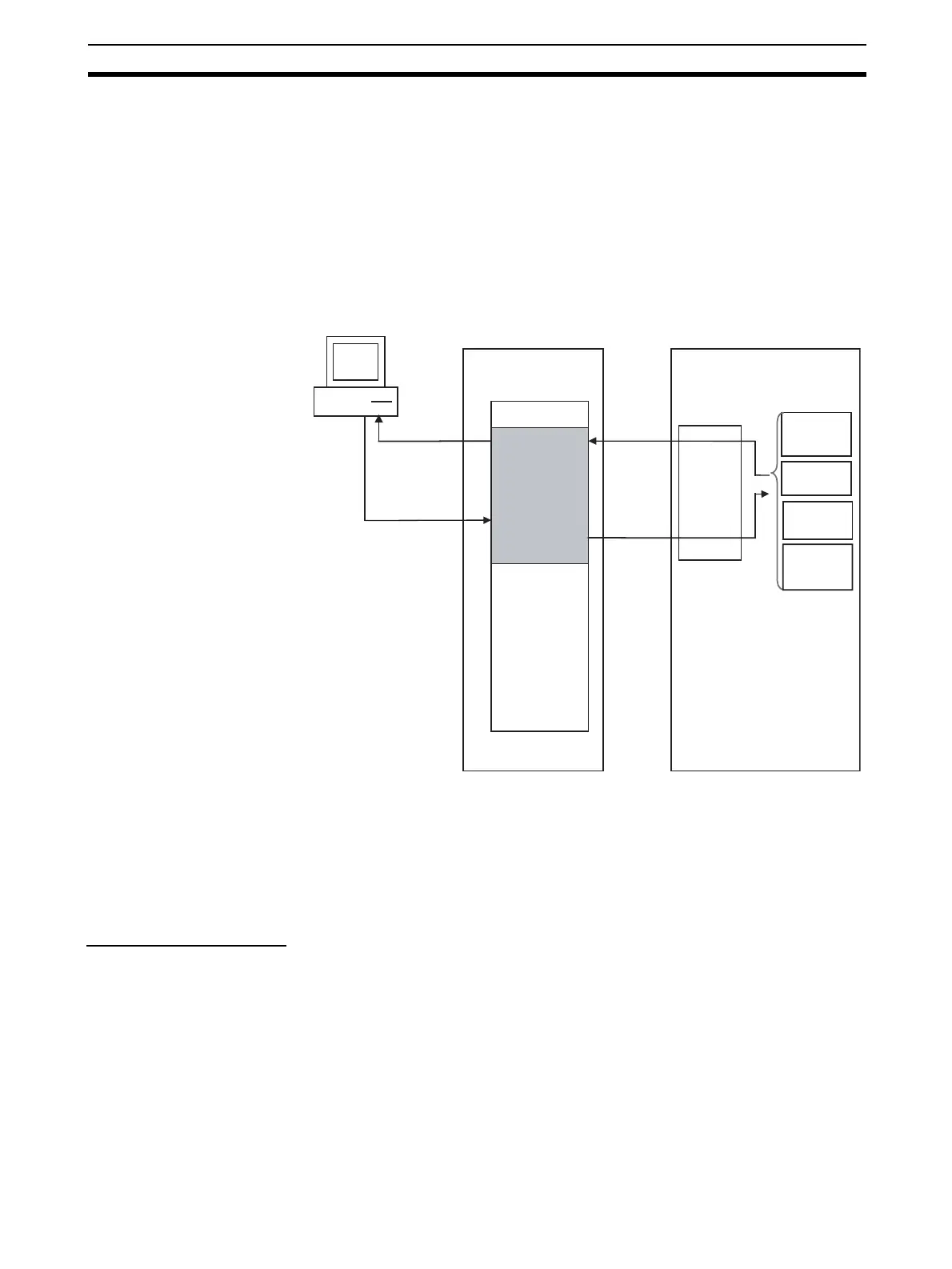
Data Exchange with
SCADA Software
Commercially available SCADA software can also be used to read and write
function block data for the Loop Controller. CSV tags can be specified from
the SCADA software to read and write ITEM data allocated for the HMI in the
CPU Unit’s EM area from control, operation, external controller, and the Sys-
tem Common block. (See note 1.) The CSV tags are created with the CX-Pro-
cess Tool.
Note 1. The EM area bank to be allocated for the HMI is specified in the System
Block (Block Model 000), ITEM 050 (EM area bank to allocated for HMI
memory, 1 to 12).
2. User Link Table tags can be treated as CSV tags just like the HMI data de-
scribed above. By specifying these tags, the I/O memory in the CPU Unit
can be read and written from the SCADA software.
2) Internal Processing • Prepare a data sheet for the function blocks shown below on CX-Process
Tool, and store the data sheet on the Loop Controller. The function block
data sheet describes: (a) software wiring of each function block and (b)
parameters in each function block.
CPU Unit
EM Area
Loop Controller
I/O memory
SCADA software
Set CSV tags
and read
Set CSV tags
and write
Control Block
ITEMs
Operation
Block ITEMs
Each
operation
cycle
HMI
data
area
External
Controller
ITEMs
Block
System
Common
block ITEMS