67
Basic Procedure for Using the Loop Controller Section 1-5
2. Decide on the PLC system configuration.
This mainly involves selection of the Analog Input and Output Units.
See 1-2 Configuration of Instrumentation System.
See Section 3 Mechanism of the Loop Controller.
3. Select the required function blocks.
See 1-4 How to Use Function Blocks for Specific Operations.
See Section 3 Mechanism of the Loop Controller.
4. Decide on the function block system configuration.
5. Assess the LCB load rate and the external I/O response cycle.
See 1-2 Configuration of Instrumentation System.
See 3-2 Description of Operation.
6. Assess fail-safe countermeasures.
See 3-5 Fail-safe Countermeasure Guidelines.
2. Preparing Function Block Data (by CX-Process Tool)
1,2,3... 1. Set up and start CX-Process Tool.
Refer to CX-Process Tool Operation Manual.
2. Set the System Common block data.
(For example, set the operation cycle and leading Data Memory address
for the Node Terminals.)
Refer to the Function Block Reference Manual.
3. In CX-Process Tool, wire the analog signals between the Selector blocks
(analog signals and accumulated value signals only).
Refer to the CX-Process Tool Operation Manual.
4. Set the ITEMs in each function block.
(If necessary, program step ladder commands in the Step Ladder Program
block including contact signals.)
Refer to CX-Process Tool Operation Manual.
Refer to the Function Block Reference Manual.
Note Set function block initial setting parameters (refer to the item “(S): Initial set-
ting data” describing how to read/write in the Function Block Reference Man-
ual) on CX-Process Tool.
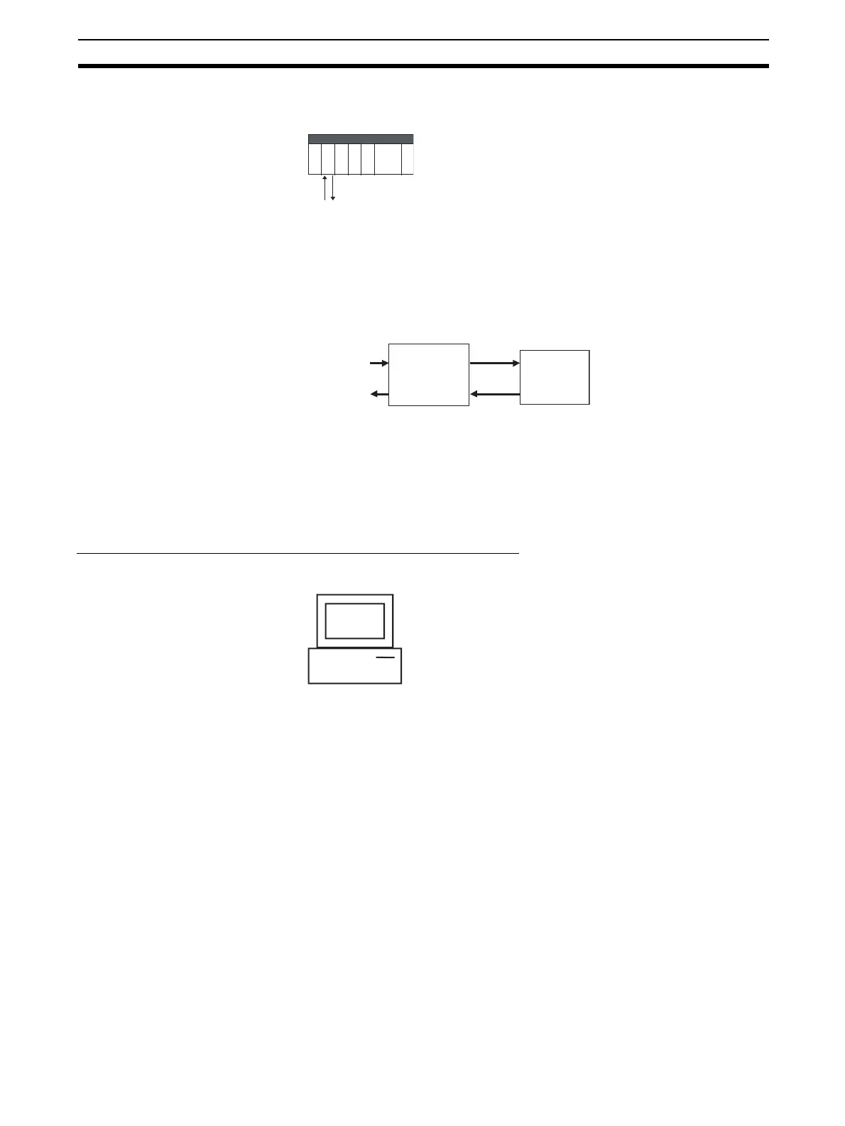
AI 4-point/AO
4-point Terminal
PV
Basic PID
Block
Model 011
Analog input
MV
nalog output
Prepare the function bloc
data on CX-Process Tool
running on the computer.