7-5SectionPulse Inputs
95
devices with high-speed counters and perform processing according to the PV of the
count. The following processes are possible.
Process
Description
Target value
interrupts
A subroutine is executed as interrupt processing when the
high-speed counter PV equals a target value.
Bit pattern
outputs for range
comparisons
A user-set bit pattern is output internally when the high-speed
counter PV is within a specified range.
Note Interrupts cannot be generated for range comparisons. Only bit patterns are out-
put. Use the bit patterns to trigger other processing as required.
The rate of change or frequency of a high-speed counter PV can also be mea-
sured from the program as required.
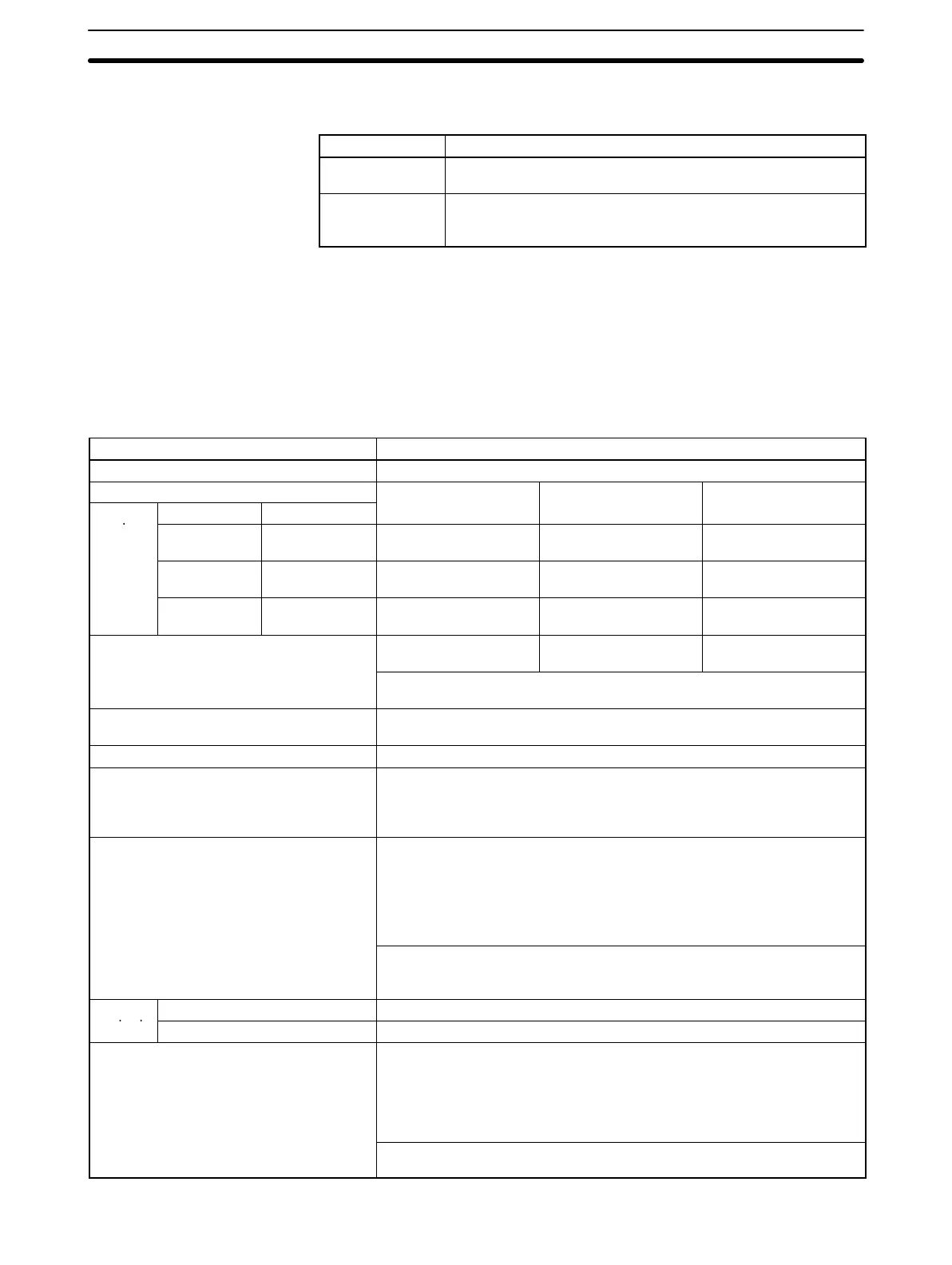
7-5-3 Specifications
Item Specification
Number of counters 2 (one for each pulse input port)
Pulse input mode (Set in Unit Setup Area.)
Differential-phase Increment/decrement Pulse + direction
Input pin
Port 1 Port 2
numbers
24 V: B2 (A1)
5 V: A2 (A1)
24 V: B8 (A7)
12 V: A8 (A7)
Phase A Increment pulse Pulse
24 V: B4 (A3)
5 V: A4 (A3)
24 V: B10 (A9)
12 V: A10 (A9)
Phase B Decrement pulse Direction pulse
24 V: B6 (A5)
5 V: A6 (A5)
24 V: B12 (A11)
12 V: A12 (A11)
Phase Z Reset pulse Reset pulse
Input method
Differential-phase; x1,
x2, x4 (switchable)
Single-phase x 2 Single-phase +
direction
Set in Unit Setup Area.
(Port 1: Bits 00 to 03 of DM 6605, port 2: Bits 00 to 03 of DM 6607)
Counter frequency (set separately for each
port)
50 kHz (default) or 200 kHz
Counting mode Linear Mode or Ring Mode (Set in Unit Setup Area.)
Counter values Linear Mode: 8000 0000 to 7FFF FFFF Hex
Ring Mode: 0000 0000 to Ring set value (Hex)
(The ring set value is set in Unit Setup Area between 0000 0001 and FFFF
FFFF Hex.)
High-speed counter PV storage locations
Port 1: AR 01 (upper bytes) and AR 00 (lower bytes)
Port 2: AR 03 (upper bytes) and AR 02 (lower bytes)
Target value or range comparison can be performed for the above values.
These values are updated during the I/O refresh period of the
Customizable Counter Unit. The stored data can be read using the PRV
instruction.
Stored Data (8-digit hexadecimal)
Linear Mode: 8000 0000 to 7FFF FFFF Hex
Ring Mode: 0000 0000 to Ring set value (Hex)
Control
Target value comparison Up to 48 target values and interrupt subroutines registered.
method
Range comparison Up to 16 upper limits, lower limits, and output bit patterns registered.
Counter reset
Phase Z Signal + Software Reset
The counter is reset on the phase-Z signal if the Reset Bit is ON.
Software Reset
The counter is reset when the Reset Bit is turned ON.
The counter reset methods is set in Unit Setup Area.
Reset Bit
Port 1: AR 0901, port 2: AR 0909