8-3SectionCycle Time
123
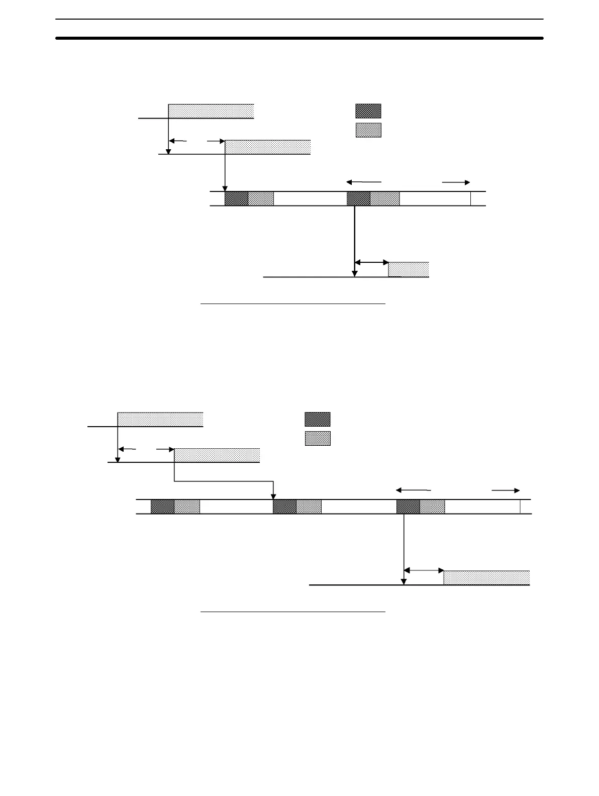
The Customizable Counter Unit responds most quickly when it receives an input
signal just prior to the input refresh phase of the cycle, as shown in the illustration
below.
Input ON delay
Instruction execution
Cycle time
With cyclic output refresh
I/O refresh
Overseeing, etc.
Output point
Input
point
Input
bit
Internal
processing
Instruction execution
Output ON
delay
When cyclic output refreshing is used:
Minimum I/O response time = 0.05 + 0.101 + 0.1 = 0.251 ms
Note Faster response times (100 µs standard) can be achieved by using input inter-
rupts and the IORF instruction.
The Customizable Counter Unit takes longest to respond when it receives the
input signal just after the input refresh phase of the cycle, as shown in the illustra-
tion below. In that case, a delay of approximately one cycle will occur
I/O refresh
Overseeing, etc.
Input ON delay
Input
point
Input
bit
Internal
processing
Instruction execution
Instruction execution
Output ON
delay
Output point
With cyclic output refresh
Instruction execution
Cycle time
When cyclic output refreshing is used:
Maximum I/O response time = 0.05 + 0.202 + 0.1 = 0.352 ms
8-3-4 Interrupt Processing Time
This section explains the processing times involved from the time an interrupt is
executed until the interrupt processing routine is called, and from the time an in-
terrupt processing routine is completed until returning to the original position.
The explanation applies to the following four types of interrupts: Input interrupts,
interval timer interrupts, high-speed counter interrupts, and pulse output inter-
rupts. Refer to relative sections in Section 7 Special Functions for details on op-
eration.
Minimum I/O Response
Time
Maximum I/O Response
Time