6-1SectionOverview
64
6-1 Overview
6-1-1 I/O Memory Areas
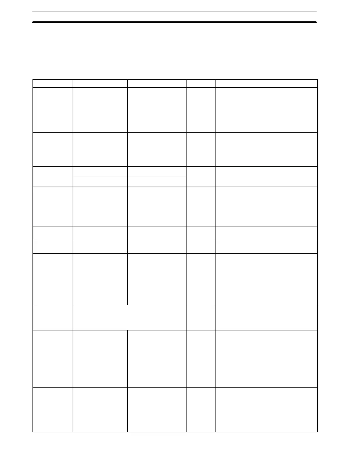
Data area Word addresses Bit addresses Size Function
Input Area IR 000 IR 00000 to IR 00011 12 bits Bits in the Input Area are allocated to in-
put terminals. These allocations are fixed
and cannot be changed.
IR 00000 to IR 00003 can be used either
as normal inputs or as interrupt inputs.
Interrupt inputs are used in Input Interrupt
Mode or Counter Mode.
Output Area IR 001 IR 00100 to IR 00107 8 bits Bits in the Output Area are allocated to
output terminals. These allocations are
fixed and cannot be changed.
IR 00108 to IR 00115 can also be used
as work bits in programming.
Work Area
IR 002 to IR 049 IR 00200 to IR 04915
1,088 bits Work bits do not have any specific func-
tion and they can be freely sed within
IR 200 to IR 219 IR 20000 to IR 21915
on, an
ey can
e
ree
y use
w
n
the program.
SR Area SR 220 to SR 255 SR 22000 to SR 25507 568 bits These bits serve specific functions such
as flags and control bits.
SR 230 to SR 239 are used to exchange
general-purpose data with the memory in
the CPU Unit’s CIO Area allocated to the
Customizable Counter Unit.
AR Area AR 00 to AR 27 AR 0000 to AR 2715 448 bits These bits serve specific functions such
as flags and control bits.
TR Area --- TR 0 to TR 7 8 bits These bits are used to temporarily store
ON/OFF status at program branches.
LR Area LR 00 to LR 31 LR 0000 to LR 3115 256 bits These bits are used to exchange general-
purpose data with the CPU Unit. Cyclic
data transfers can be set up with user-set
words in the CPU Unit.
Up to 32 I/O words of data can be ex-
changed. The LR Area allocations are set
in DM 6601 to DM 6604 of the Unit Setup
Area in the Customizable Counter Unit.
Timer/Counter
Area
TIM/CNT 000 to TIM/CNT 255
(timer/counter numbers)
256 bits The timer numbers in the Timer/Counter
Area are allocated to create timers and
counters. The same numbers are used
for both timers and counters.
Read/Write
portion of DM
Area
DM 0000 to DM 6143 (Designation not pos-
sible in bit units.)
6,144
words
DM Area data can be read and written
using instructions or the Programming
Device in word units only. Word values
are retained when power is turned OFF
or when the operating mode is switched.
The contents of the DM Area can be
backed up in flash memory by turning ON
a control bit (SR 25200). Data can be
read from flash memory using XFER(70).
EM Area EM 0000 to EM 2047 (Designation not pos-
sible in bit units.)
2,048
words
EM area data can be read and written
using instructions or the Programming
Device in word units only.
It is possible to set whether or not word
values are retained when power is turned
OFF or when the operating mode is
switched.