3-3SectionWiring
28
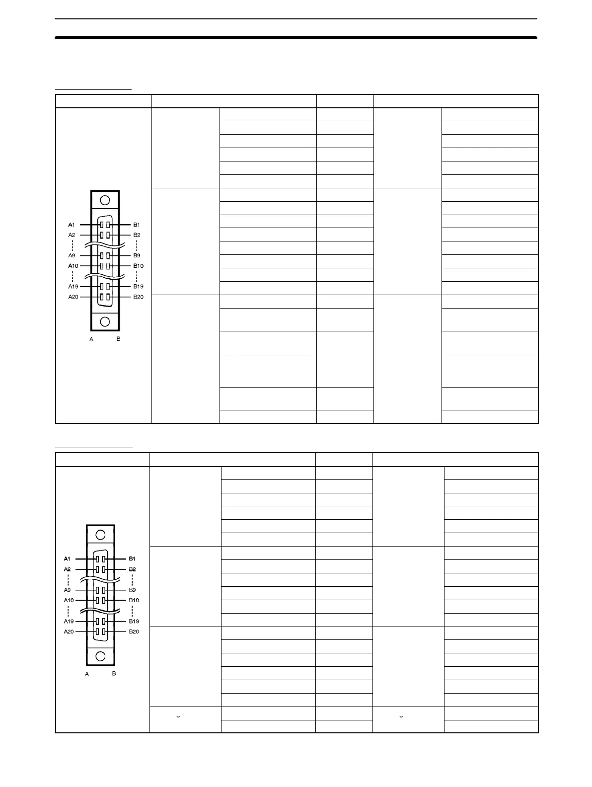
3-3-2 Special I/O Connector Pin Arrangement
CS1W-HCP22
Pin arrangement Row A Pin number Row B
Pulse input 1
Phase A LD–/0 V 1
Pulse input 1
Phase A LD+
Phase A 5 V 2 Phase A 24 V
Phase B LD–/0 V 3 Phase B LD+
Phase B 5 V 4 Phase B 24 V
Phase Z LD–/0 V 5 Phase Z LD+
Phase Z 5 V 6 Phase Z 24 V
Pulse input 2
Phase A LD–/0 V 7
Pulse input 2
Phase A LD+
Phase A 12 V 8 Phase A 24 V
Phase B LD–/0 V 9 Phase B LD+
Phase B 12 V 10 Phase B 24 V
Phase Z LD–/0 V 11 Phase Z LD+
Phase Z 12 V 12 Phase Z 24 V
Not used. 13 Not used.
Not used. 14 Not used.
Pulse output 1
CW 15
Pulse output 2
CW
CW (with 1.6-kΩ
resistance)
16 CW (with 1.6-kΩ
resistance)
CCW/one-shot pulse
output
17 CCW/one-shot pulse
output
CCW/one-shot pulse
output (with 1.6-kΩ
resistance)
18 CCW/one-shot pulse
output (with 1.6-kΩ
resistance)
Output power supply:
24 V
19 Output power supply:
24 V
Common 20 Common
CS1W-HCA22
Pin arrangement Row A Pin number Row B
Pulse input 1
Phase A LD–/0 V 1
Pulse input 1
Phase A LD+
Phase A 5 V 2 Phase A 24 V
Phase B LD–/0 V 3 Phase B LD+
Phase B 5 V 4 Phase B 24 V
Phase Z LD–/0 V 5 Phase Z LD+
Phase Z 5 V 6 Phase Z 24 V
Pulse input 2
Phase A LD–/0 V 7
Pulse input 2
Phase A LD+
Phase A 12 V 8 Phase A 24 V
Phase B LD–/0 V 9 Phase B LD+
Phase B 12 V 10 Phase B 24 V
Phase Z LD–/0 V 11 Phase Z LD+
Phase Z 12 V 12 Phase Z 24 V
---
Not used. 13
---
Not used.
Not used. 14 Not used.
Not used. 15 Not used.
Not used. 16 Not used.
Not used. 17 Not used.
Not used. 18 Not used.
Analog output 1
Voltage output (+) 19
Analog output 2
Voltage output (+)
Voltage output (–) 20
Voltage output (–)