8-3SectionCycle Time
114
The effects of the cycle time on Customizable Counter Unit operation are as
listed below.
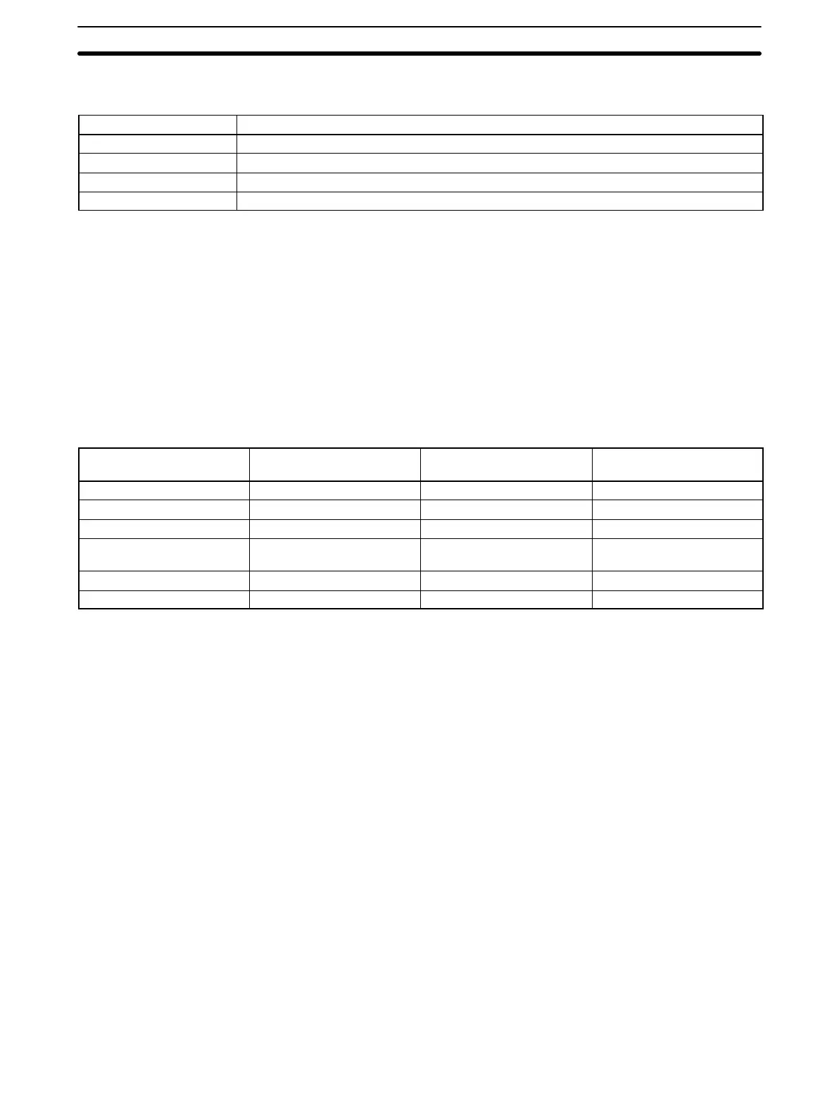
Cycle time Operation conditions
10 ms or longer CYCLE TIME OVER detected and SR 23509 turns ON. TIMH will not time accurately.
20 ms or longer Programming using the 0.02-second Clock Bit (SR 25401) may be inaccurate.
50 ms or longer Fatal error occurs if the cycle time monitoring time in DM 6618 is set to 50 ms (default).
100 ms or longer Fatal error occurs if the cycle time monitoring time in DM 6618 is set to the maximum value.
Note User Setup Area word DM 6655 can be used to disable detection of CYCLE
TIME OVER error.
In this example, the cycle time is calculated for a Customizable Counter Unit.
The conditions are as follows:
The operating conditions are as follows:
Model: CS1W-HIO01
User’s program: 2,000 instructions (consisting of LD and OUT instructions)
Cycle time: Variable (no minimum set)
Note The average processing time for a single instruction in the user’s program is as-
sumed to be 0.8 µs.
The cycle times are as shown in the following table.
Process Calculation method Time with peripheral
device
When Peripheral
Connection Switch is OFF
Overseeing 0.016 ms 0.016 ms
Program execution 0.8 × 2000 (µs) 1.6 ms 1.6 ms
Cycle time calculation 0.033 ms 0.033 ms
I/O refresh in Customizable
Counter Unit
0.025 ms 0.025 ms
Peripheral servicing 0.2 ms 0.003 ms
Cycle time (1) + (2) + (3) + (4) + (5) 1.874 ms 1.677 ms
Note 1. The cycle time can be automatically read from a Programming Device.
2. The maximum and current cycle time are stored in AR 26 and AR 27.
3. The cycle time can vary with actual operating conditions and will not neces-
sarily agree precisely with the calculated value.
4. The cycle time will be a little longer when bits are force-set/reset.
Cycle Time and
Operation
Cycle Time Example