2-1SectionPerformance Specifications
14
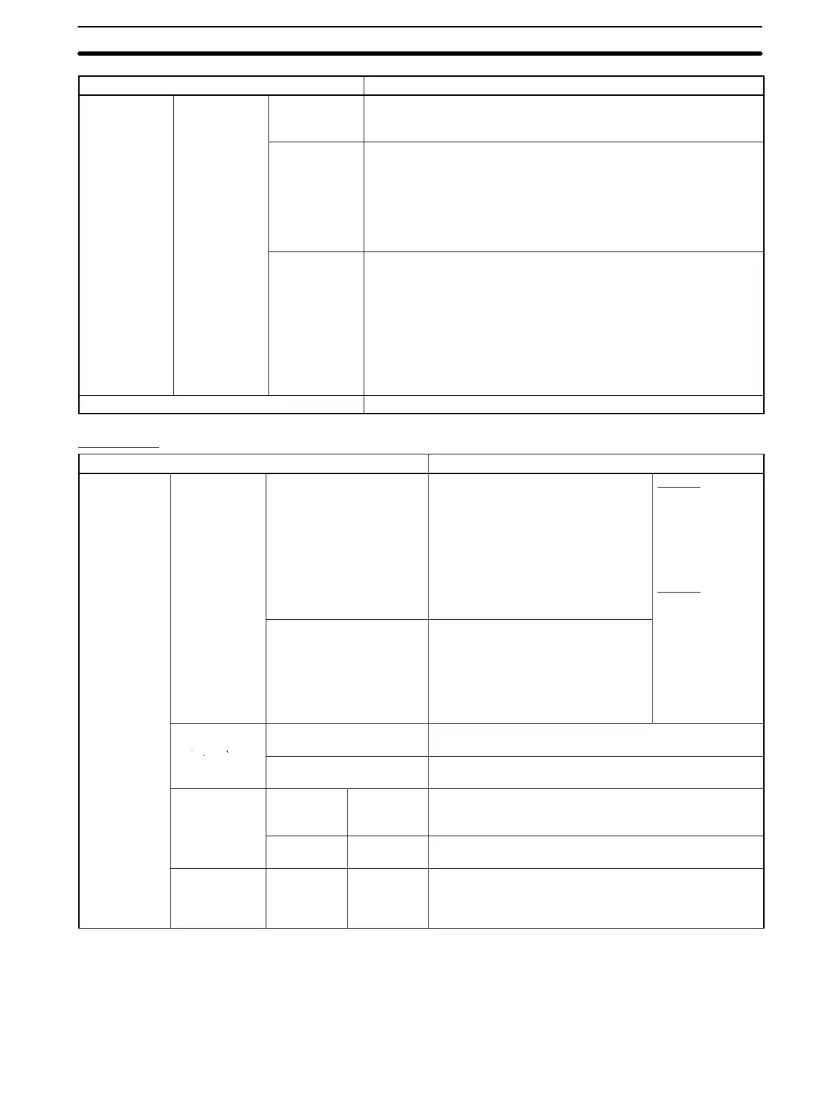
Item Specifications
Other memory
areas
Read-only
portion of DM
Area
Error Log Area 56 words: DM 6144 to DM 6199
Data in this area is held (with super-capacitor backup) at power
interruptions or when the mode is switched.
General-pur-
pose read-only
area
400 words: DM 6200 to DM 6599
Data in this area is held (in flash memory) at power interruptions or
when the mode is switched.
Writing to this area is not possible using instructions; it is only pos-
sible from the Programming Device. (Reading is possible with either
method.) Data in this area is protected from being changed by the
ladder program.
Unit Setup
Area
56 words: DM 6600 to DM 6655
This area is for making the initial settings for the functions of the
Customizable Counter Unit at a software level.
Data in this area is held (in flash memory) at power interruptions or
when the mode is switched.
Writing to this area is not possible using instructions; it is only
possible from the Programming Device. (Reading is possible with
either method.) Data in this area is protected from being changed by
the ladder program.
Trace memory None
Functions
Item Specifications
Types of
interrupts
Input interrupts
(4 points max.)
Input Interrupt Mode Interrupt is executed in response to
input to the Unit’s built-in input points
(input bits 00000 to 00003). Interrupts
can be executed when the
corresponding input turns ON, OFF,
or both. The response time between
the input conditions being satisfied
and execution of the interrupt
program is 0.08 ms (for execution at
ON).
Note 1:
Specify the mode
as either Input
Interrupt Mode or
Counter Mode
using the INT
instruction.
Note 2:
Specify ON, OFF,
Counter Mode Interrupt is executed after input is
received via the Unit’s built-in input
points a certain number of times. The
number of times is counted
decrementally when the
corresponding input turns ON, OFF,
or both.
Setup Area.
Interval timer
interrupt (1
Scheduled Interrupt Mode Program is interrupted at regular intervals measured by
one of the Unit’s internal timers.
point)
One-shot Interrupt Mode Program is interrupted once after a certain time
measured by one of the Unit’s internal timers.
CS1W-HCP22
(pulse I/O)
Pulse inputs
(high-speed
counter)
Target value
interrupts
Interrupt is executed when the high-speed counter PV is
equal to a target value set with the CTBL instruction.
Pulse
outputs
Target value
interrupts
Interrupt is executed when the pulse output PV is equal
to a target value set with the CTBL instruction.
CS1W-HCA22
(pulse inputs
and analog
outputs)
Pulse inputs
(high-speed
counter)
Target value
interrupts
Interrupt is executed when the high-speed counter PV is
equal to a target value set with the CTBL instruction.