3-3SectionWiring
30
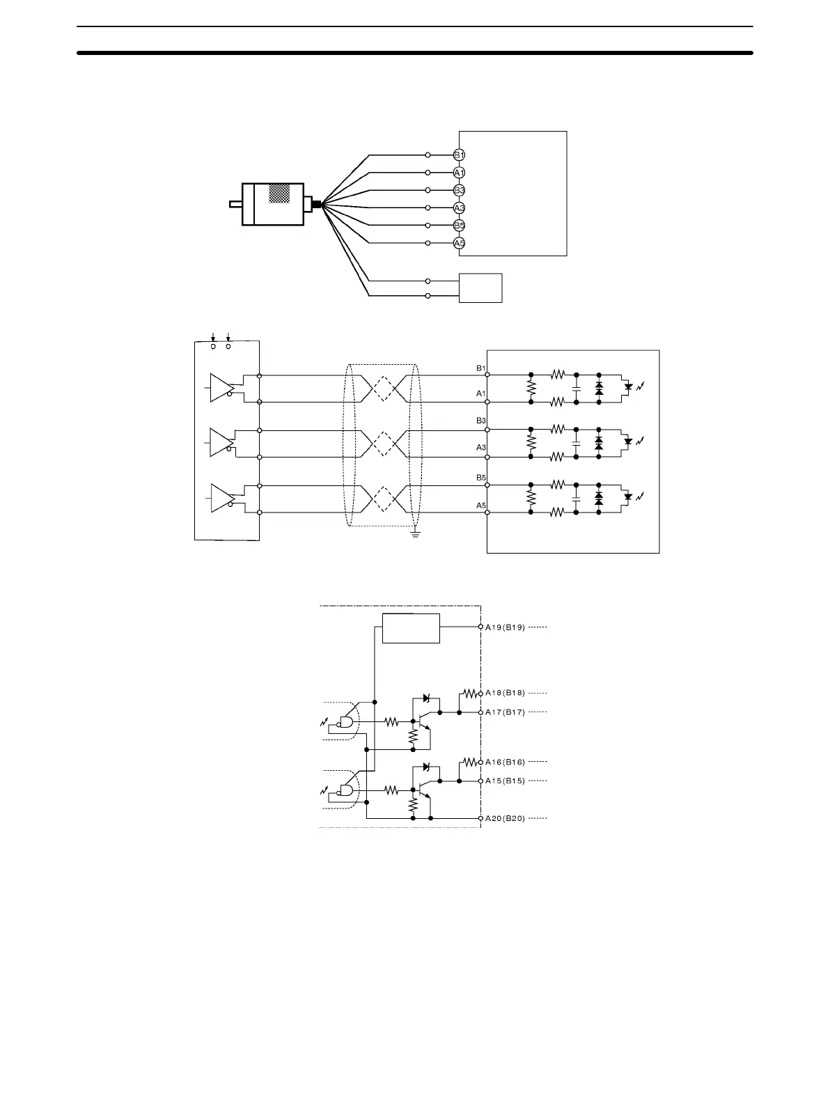
The wiring for when the encoder has a line-driver output (Am26LS31 or equiva-
lent) is shown below.
Encoder
Example: E6B2-CWZ1X
Line driver output
Black
Black with
stripes
White
White with
stripes
Orange
Brown
A+
A–
B+
B–
Z+
Customizable Counter Unit
Blue
Power supply
Encoder
Shielded twisted-pair cable
Customizable Counter Unit
Orange with
stripes
Z–
5 VDC
0 V
(Differential-phase Input Mode)
(Pulse input 1: Phase A, LD+)
(Pulse input 1: Phase A, LD–)
(Pulse input 1: Phase B, LD+)
(Pulse input 1: Phase B, LD–)
(Pulse input 1: Phase Z, LD+)
(Pulse input 1: Phase Z, LD–)
5-VDC power supply
+5 V
0 V
A+
A–
B+
B–
Z+
Z–
Pulse Outputs (CS1W-HCP22)
Customizable Counter Unit
Constant-
voltage
circuit
Output power supply, 24 VDC
CCW pulse output (with 1.6-kΩ resistance)
CCW pulse output
CW pulse output (with 1.6-kΩ resistance)
CW pulse output
Common (0 V)
Name
Port 1
Pin No.
1.6 kΩ
(1/2 W)
1.6 kΩ
(1/2 W)