3-3SectionWiring
33
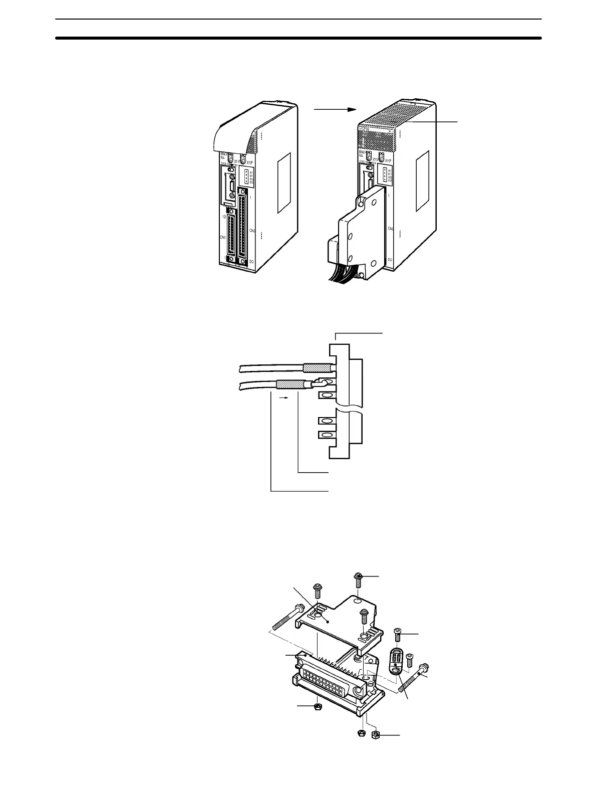
performing wiring. After wiring has been completed, remove the label to
allow proper heat dissipation.
Hook
After wiring
Remove the label.
3. When soldering, take care not to short the terminal to the neighboring one.
Cover the soldered part with an insulating tube.
Soldered-type connector
included with Unit
Insulating tube
Wire (0.2 to 0.13 mm
2
)
Note Be sure to check that the output power supply is not connected in reverse.
4. Assemble the connector (included or purchased separately) as shown
below. The shape of the 40-pin connector is different to that shown in the
diagram.
Connector cover
Small screws (3)
Small screws (2)
Connector lock screw
Cable clamp
Nuts (2)
Nuts (3)
Socket