6-2SectionDetails
68
6-2-5 LR Area
This area can be used for data exchange with user-set words (in the CIO, WR,
AR, HR, DM, or EM Area) in the CPU Unit.
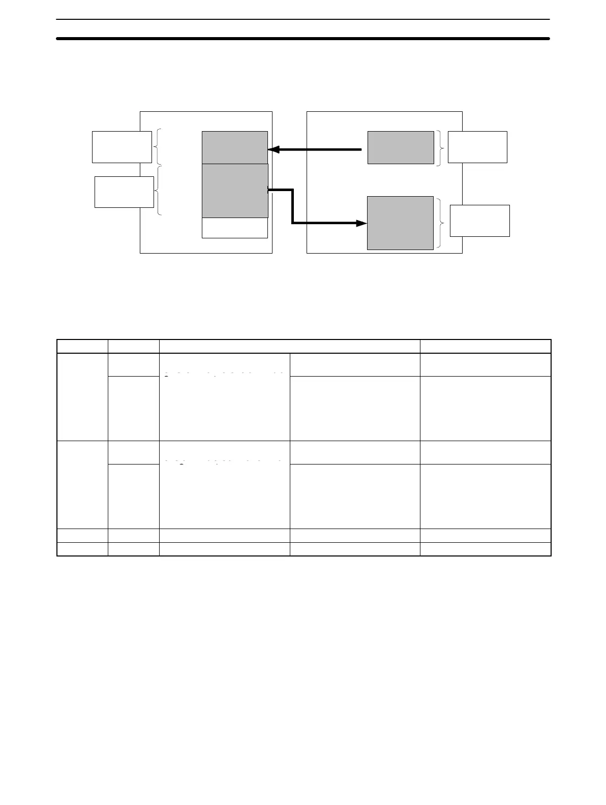
Customizable Counter Unit CPU Unit
LR 00
First word
of output
area
LR Area
Output area
Unused words
User-defined
address
User-defined
address
General-purpose area
General-purpose
output area
General-purpose
input area
Number of re-
freshed words
in output area
Number of re-
freshed words
in input area
Input area
Number of re-
freshed words
in input area
Number of re-
freshed words
in output area
The words used in the CPU Unit are set in the Unit Setup Area (DM 6601 to
DM 6604) as shown below. The input and output areas in the LR Area are allo-
cated in the order input area → output area starting from the first word of the LR
Area. The number of words in the areas are determined by the refresh settings.
General-purpose I/O is exchanged between the LR Area and the user-set words
in the CPU Unit, as shown in the following table.
Address Bits Function Contents
DM 6601
00 to 07
Input area (input from the
CPU Unit to the Customizable
Number of refreshed words 00 (BCD): Not refreshed
01 to 32 (BCD): 1 to 32 words
08 to 15
Counter Unit)
CPU Unit area 00 (BCD): CIO
01 (BCD): WR
02 (BCD): AR
03 (BCD): HR
04 (BCD): DM
05 (BCD): EM
DM 6602
00 to 07
Output area (output from the
Customizable Counter Unit to
Number of refreshed words 00 (BCD): Not refreshed
01 to 32 (BCD): 1 to 32 words
08 to 15
the CPU Unit)
CPU Unit area 00 (BCD): CIO
01 (BCD): WR
02 (BCD): AR
03 (BCD): HR
04 (BCD): DM
05 (BCD): EM
DM 6603 00 to 15 Input area First word in CPU Unit area 0000 to 9999 (BCD)
DM 6604 00 to 15 Output area First word in CPU Unit area 0000 to 9999 (BCD)
Note When LR Area bits are not being used for the above functions, they can be used
as work bits.
6-2-6 Timer/Counter Area
This area is used to manage the TIM, TIMH(15), TMHH(––), CNT, and
CNTR(12) instructions. The same numbers are used for timers and counters; do
not use the same number twice even for different instructions.
If TIM/CNT number is designated for word data, it will access the present value
(PV); if it is used for bit data, it will access the Completion Flag for the timer/
counter.
The Completion Flag turns ON when the PV of the timer/counter that is being
used goes to 0.
Interrupt processing is not performed for TIMH(15), i.e., timing processing is
performed only when the instructions is executed. If the cycle time is longer than
10 ms, counting may not be reliable.