6-3SectionSR Area
72
Address Controlled
by
FunctionBits
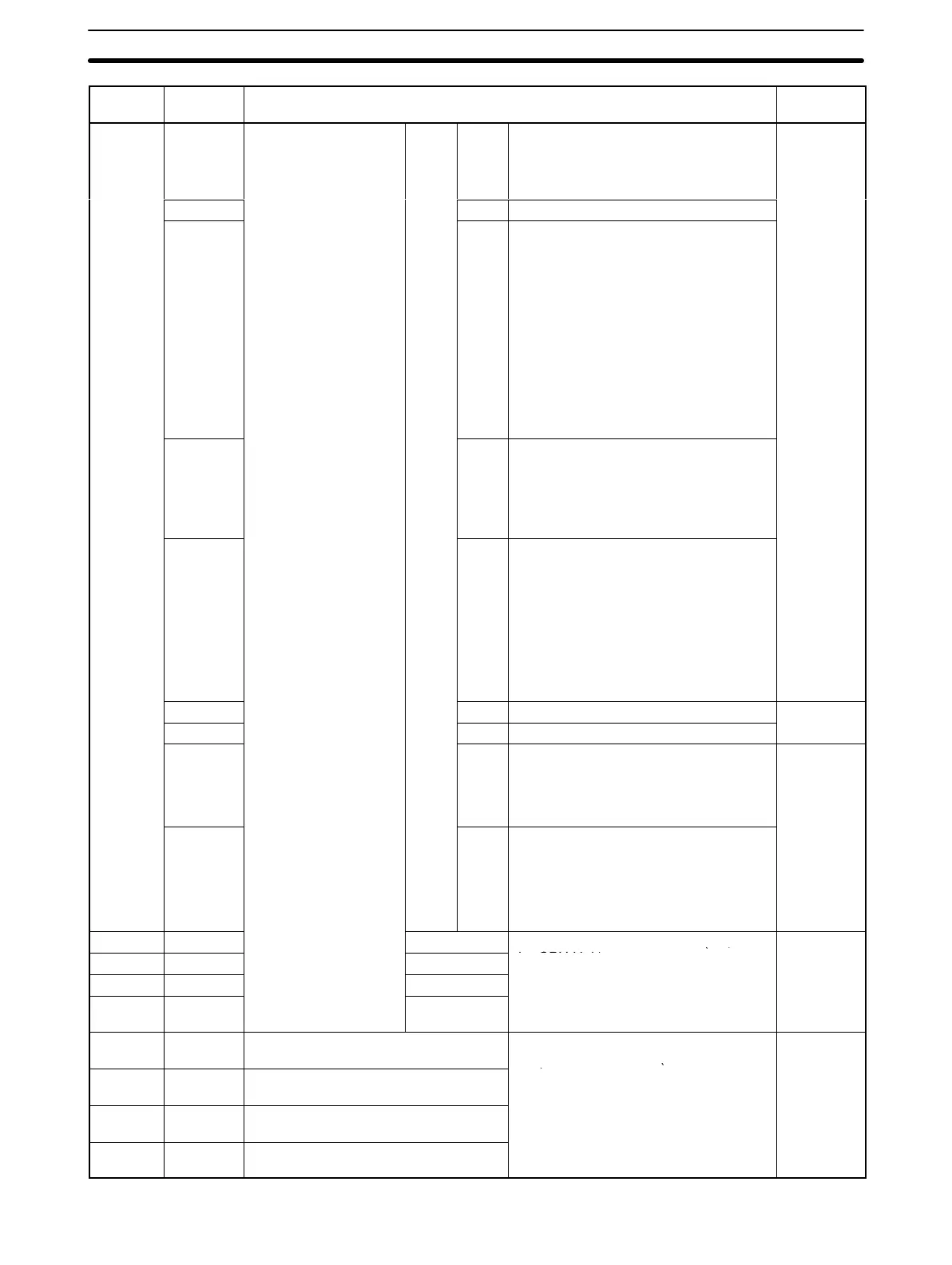
SR 235
00 to 07
For exchanging data
with words allocated in
CPU Unit’s CIO Area
(from Customizable
n+5
00 to
07
Unit error code
Note: The error codes are also stored
in bits 00 to 07 of the error information
portion of error logs.
Unit
08
oun
er
n
o
Unit)
08 (Reserved by system.)
09
09 Unit CYCLE TIME OVER (non-fatal
error)
OFF: No error (cycle time less than
10 ms)
ON: CYCLE TIME OVER error (cycle
time more than 10 ms)
Note: Valid only when the system is set
to detect CYCLE TIME OVER (set in
DM 6655). When the cycle time is
exceeded (more than 10 ms), the Unit
error code F8 is stored in SR 23500 to
SR 23507.
10 10 Non-fatal Unit error (including FAL
instruction execution)
OFF: No non-fatal error
ON: Non-fatal error occurred (e.g., Unit
setup error, fatal CPU Unit error)
11 11 Unit fatal error (including FALS
instruction execution)
OFF: None of the errors below have
occurred.
ON: One of the following fatal errors
has occurred: FALS instruction
executed; no END instruction; special
I/O error, Cycle Monitor Time Exceeded
(set in DM 6618 in the Unit Setup Area).
12 12 (Reserved by system.)
---
13 13 (Reserved by system.)
14 14 Unit busy
OFF: The Unit is not busy.
ON: The Unit is busy (i.e., performing
initial processing).
Unit
15 15 Unit operating status
OFF: STOP (PROGRAM mode)
ON: RUN (RUN or MONITOR mode)
Note: When this bit is ON, the OPN
indicator on the front of the Unit lights.
SR 236 00 to 15 n+6
General-purpose input words (i.e., to
User
SR 237 00 to 15 n+7
the CPU Unit)
SR 238 00 to 15 n+8
SR 239 00 to 15 n+9
SR 240 00 to 15 Input Interrupt 0 (IR 00000) Counter
Mode SV
Counter SVs when input interrupts are
used in Counter Mode (0000 to FFFF
User
SR 241 00 to 15 Input Interrupt 1 (IR 00001) Counter
Mode SV
Hex).
Note: When input interrupts are not
SR 242 00 to 15 Input Interrupt 2 (IR 00002) Counter
Mode SV
u
u
used in Counter Mode, these bits can
be used as work bits.
SR 243 00 to 15 Input Interrupt 3 (IR 00003) Counter
Mode SV