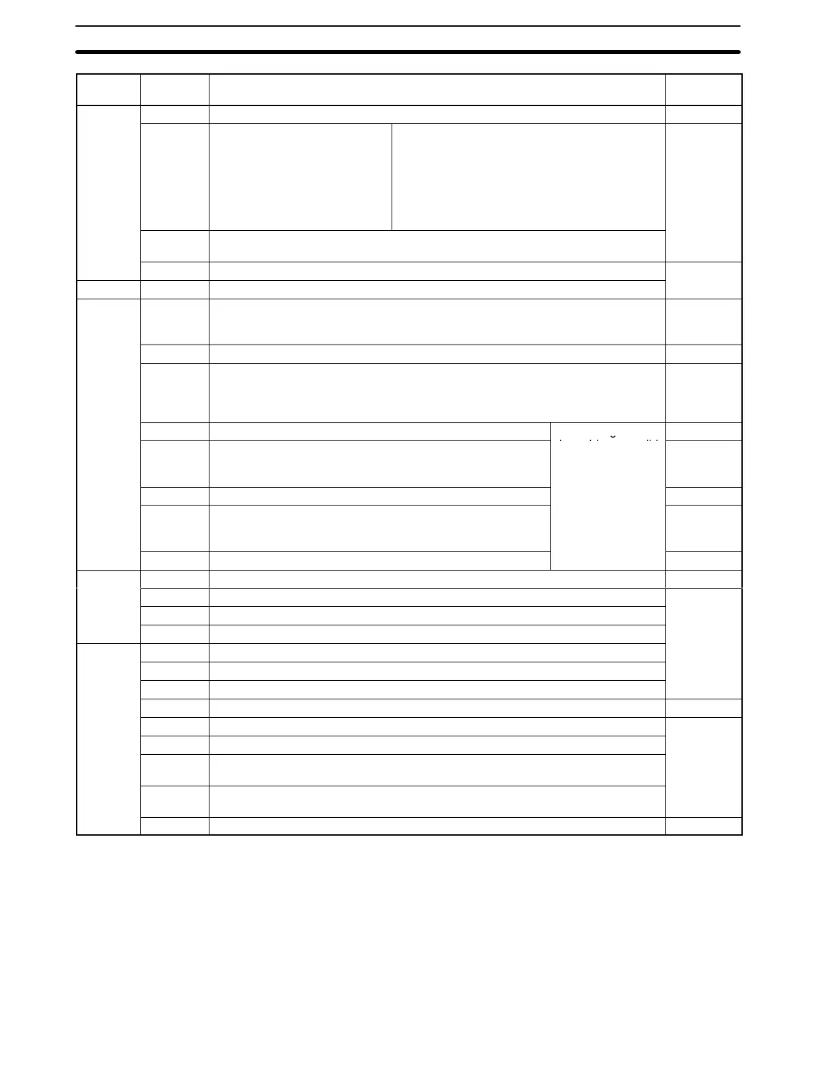
6-3SectionSR Area
75
Address Controlled
by
FunctionBits
SR 250
00 to 07 (Reserved by system.) ---
08 to 11 Peripheral port error code 0 Hex: No error
1 Hex: Parity error
2 Hex: Framing error
3 Hex: Overrun error
Note: When a Programming Device is
connected using peripheral bus
communications, F Hex is stored here.
Unit
12 Peripheral Port Communications Error
Turns ON when there is a peripheral port communications error.
13 to 15 (Reserved by system.)
---
SR 251 00 to 15 (Reserved by system.)
SR 252
00 DM Area to Flash Memory Transfer Bit
Turn ON this bit to save the contents of DM Area words DM 0000 to DM 6143 to
flash memory. The bit automatically turns OFF after execution.
User
01 to 07 (Reserved by system.) ---
08 Peripheral Port Reset Bit
Turn ON this bit to reset the peripheral port. (Invalid if the peripheral port is used
for peripheral bus communications.) The bit automatically turns OFF after
execution.
User
09 (Reserved by system.)
The settings of
---
10 Unit Setup Area Reset Bit
Turn this bit ON to reset the Unit Setup Area (DM 6600 to
DM 6655). The bit automatically turns OFF after execution.
these bits are valid
only when the
Customizable
User
11 to 13 (Reserved by system.)
oun
er
n
s
n
PROGRAM mode.
---
14 Error Log Reset Bit
Turn this bit ON to clear the error log. The bit automatically
turns OFF after execution.
.
User
15 (Reserved by system.) ---
SR 253
00 to 12 (Reserved by system.) ---
13 Always ON Flag
Unit
14 Always OFF Flag
15 First Cycle Flag
SR 254
00 1-minute Clock Pulse (30 seconds ON; 30 seconds OFF)
01 0.02-second Clock Pulse (0.01 seconds ON; 0.01 seconds OFF)
02 Negative (N) Flag
03 (Reserved by system.) ---
04 Overflow (OF) Flag
Unit
05 Underflow (UF) Flag
06 Differential Monitor Completion Flag
Turns ON when differential monitoring has been completed.
07 STEP Execution Flag
Turns ON for one cycle only at the start of a processed based on STEP.
08 to 15 (Reserved by system.) ---