-14-
Installation steps (Basic)
7
●Small screwdriver, Phillips #1 ●Screwdriver, Phillips #2
■ Required Tools ■
7-1
Preparation for installation
[Unit
︓
mm (in.)]
For mounting
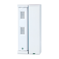
For replacing OVS-01
For wiring
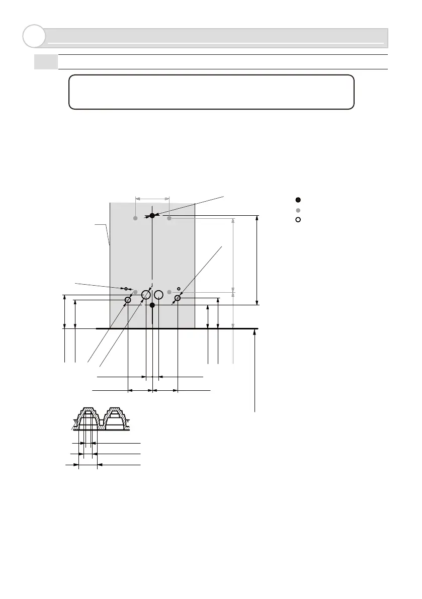
• On a square pole or a wall, drill holes to install the unit as shown below. If tapped holes cannot be made,
make pilot holes of ø4.3mm (0.17in.), and secure the unit using nuts. After making holes, deburr the surface
to preserve the waterproof property.
• When mounting the unit directly to a wall using tapping screws, consider its effect, and take appropriate
actions, such as making pilot holes, according to the target material. We cannot be held liable for any
negative effect on the target material.
M4 tap
Installation pitch
84.5 (3 11/32)
500 (20) from the ground
±1.5 (±1/16)
Φ5(13/64)
32(
1 11/32
)
22
(55/64)
Φ3(1/8)
Φ6(15/64)
Φ8(5/16) *1
29(1 5/32)
27(1 1/16)
32(1 17/64)
6(15/64) 6(15/64)
23(29/32) 24(15/16)
70(2 3/4) 34(1 11/32)
Sensor outline
Φ
2 (5/64)
Φ
4 (5/32)
Φ
8 (5/16)
*1 : Cut rubber tip to fit the appropriate cable diameter.