-31-
Signals can be selected according to the application of the output signals.
Refer to the section below and make a selection.
Detailed settings can not be made for modes othe than “Detection” .
Detection : A normal detection.
(The output state reflects the setting of Output delay, Hold timer and others.) *1
Pre-detection : Outputs a pre-detection and a normal detection both.
(The output state does not reflect the setting of Output delay, Hold timer and others.)
Mask: This is a function to send a relay output when the sensor surface is blocked by something by
vandalism and it effects to the performance of the sensor.Once the sensor is masked for more
than 30 seconds, it starts sending a relay output. Also if it recognizes it stopped masked for more
than 10 seconds, it stops sending the output.
*1: Outputs the detection status when mask detection is judged.
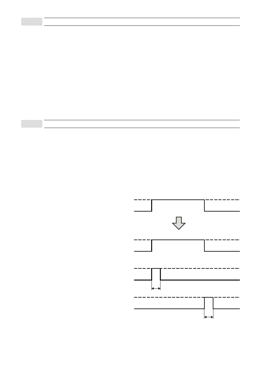
Output methods can be selected according to the connected devices.
Normally select “Holding” .
Signal characteristics for each type are shown below.
When “Pulse” is selected, the pulse time (signal width) can be adjusted.
Holding : Outputs of detection signals are held during detection.
Pulse IN : A signal is output only when a detection occurs. The pulse time can be adjusted.
Pulse OUT : A signal is output only when the detection status switches to non-detection.
The pulse time can be adjusted.
Detection
Sensor
(processed internally)
Output: Holding
Output: Pulse IN
Output: Pulse OUT
Non-detection
Detection
Non-detection
Detection
Non-detection
Pulse time
Detection
Non-detection
Pulse time
8-4-3
Mode
8-4-4
Output types and pulse time