-29-
4-6
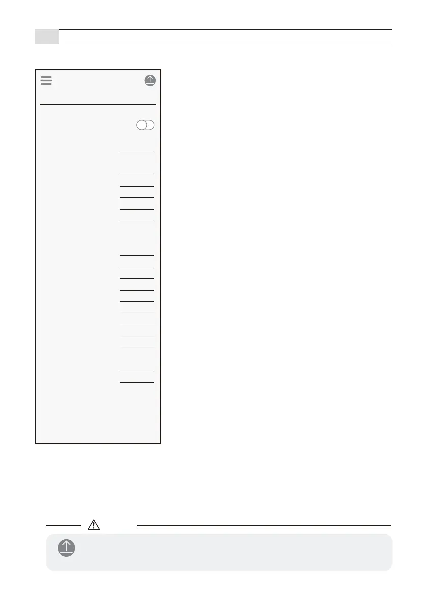
App description (Input and output screen)
- Check and change the input / output settings of the sensor.
■ Applications
Change it by selecting Menu Icon > Favorite > Select application.
● Indicator
[1] Indicator
Refer to page 30
The operation indicator is lit when the sensor makes a
detection during operation. The operation indicator can
be selected to On or Off.
● Heater
[1] Heater
Refer to page 30
Normally set this to Normal.
● Output
[3] Mode
Refer to page 31
[4] Output type
Refer to page 31
[5] Pulse time
Refer to page 31
[6] Delay
Refer to page 32
[7] Hold timer
Refer to page 3229
● RS485 (GT model does not use)
[8] RS485 channel
[9] RS485 baud rate
[10] RS485 EOL
[11] RS485 communication protocol
Set according to the connected device.
● Input
[12] Mode
[13] Contact
Set according to the connected device.
Caution
- After changing the settings, tap the send icon to send the settings to the sensor.
8-4
Input and output
Application
Indicator
Detection
Indicator
Barrier Protection 90 deg
Normal
Pulse IN
Mode
Output type
150ms
Pulse time duration
0.5s
Delay
0.5s
Hold timer
Off
EOL
Output 1
Detection
Pulse IN
Mode
Output type
150ms
Pulse time duration
0.5s
Delay
0.5s
Hold timer
0
RS485 channel
0
RS485 baud rate
0
RS485 EOL
0
RS485 protocol
Output 2
Link(OR gate)
High
Mode
Contact
Input
Heater
Heater