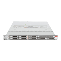
Back Panel Status Indicators, Connectors, and PCIe Slots
Call Out Description
3 USB 2.0 connectors (2)
4 SP OK LED: green
5 Service Required LED: amber
6 Power/OK LED: green
7 Power button
8 Service Required LED: Top: Fan Module (amber)
9 Service Required LED: Rear: Power Supply (amber)
10 Service Required LED: Overtemp Icon: System Over Temperature Warning (amber)
11 Storage drive 0
12 Storage drive 1
13 Storage drive 2 (Optional NVM-Express SSD)
14 Storage drive 3 (Optional NVM-Express SSD)
15 Storage drive 4 (Optional NVM-Express SSD)
16 Storage drive 5 (Optional NVM-Express SSD)
17 Storage drive 6
18 Storage drive 7
19 Optional SATA DVD Drive
Related Information
■
“Back Panel Status Indicators, Connectors, and PCIe Slots” on page 30
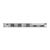
Back Panel Status Indicators, Connectors, and PCIe Slots
The following figure shows the Oracle Server X6-2 back panel and the location of status
indicators (LEDs), connectors, and PCIe slots.
For information about how to interpret the status indicators (LEDs), refer to the Oracle Server
X6-2 Service Manual.
30 Oracle Server X6-2 Installation Guide • July 2020