IG-150-EN version 04; 03/10/16
30
General description General instructions
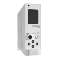
ekor.rps
The terminal numbers indicated in the previous wiring
diagrams is for units with pin type terminals. If the units
have closed type terminals, the only dierence lies on those
terminals corresponding to T6 and T9 transformers, because
V
A
, V
B
and V
C
measurement transformers, have a common
point (that is, compound voltages cannot be connected
with closed type terminals, but only single voltages can..
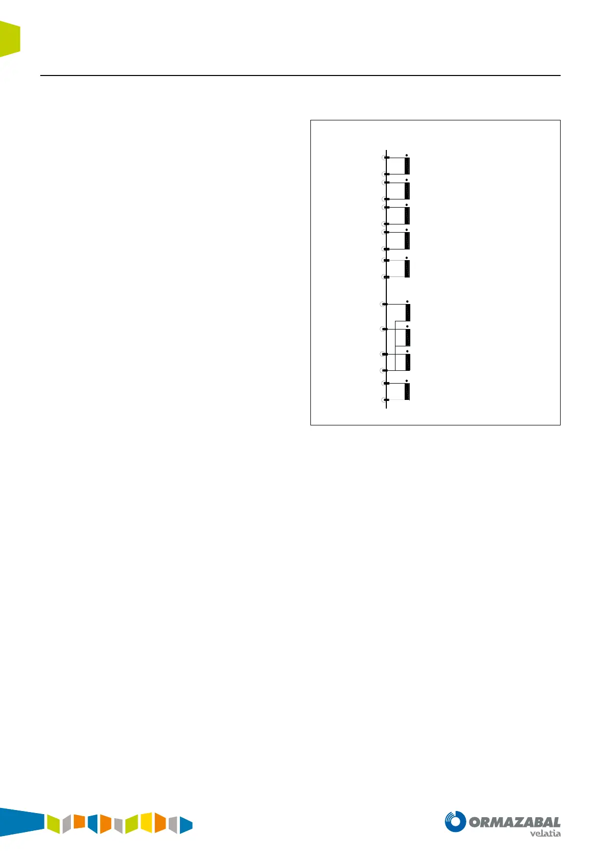
Connections of the analogue inputs in models with
closed type terminals:
14
13
12
11
8
7
6
5
4
3
2
1
T1 (IA)
T2 (IB)
T3 (IC)
T4 (IN)
T6 (TA)
T7 (TB)
T8 (TC)
X3
10
9
T5 (V or I ac. to model)
16
15
T9 (V or I ac. to model)
Figure 1.19. Connections of the analogue inputs