May 1992
xi
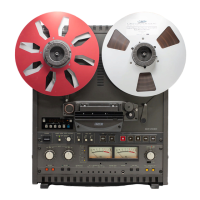
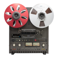
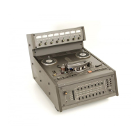
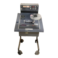
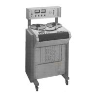
Figure 1-1 Exterior Appearance .................................. 1-2
Figure 2-1 Audio Connectors .................................... 2-3
2-2 Balanced/Unbalanced Connectors ..................... 2-4
2-3 Switch Setting on Rear Panel .......................... 2-5
2-4 Controls on the CONTROL PCB Assembly ............. 2-6
2-5 PCB Assembly Location (BIII) ......................... 2-9
2-6 AMP Section Rotation (BIII) .......................... 2-9
2-7 CONTROL PCB Assembly Rotation (BIII) ............. 2-10
2-8 PCB Assembly Location (MK
IV
-2) .................... 2-11
2-9 CONTROL PCB Assembly Rotation (MK
IV
-2) ......... 2-12
2-10 Power Connection ................................... 2-13
2-11 AC Line Voltage Connector ............................2-13
2-12 Fuse Location.........................................2-14
Figure 3-1 Tape Transport ....................................... 3-2
3-2 Transport Control Panel ............................... 3-3
3-3 Head Assembly ....................................... 3-6
3-4 Amplifier Panel (MKIV-2) ............................. 3-7
3-5 Audio Connector Panel (BIII) .......................... 3-7
3-6 Audio Connector Panel (MKIV-2) .................... 3-10
Figure 4-1 Tape Threading ....................................... 4-6
4-2 Editing a Tape ....................................... 4-10
Figure 5-1 Demagnetizing the Head .............................. 5-2
5-2 Cleaning the Head .................................... 5-3
5-3 Lubrication ........................................... 5-4
Figure 6-1 Brake Torque Measurement .......................... 6-2
6-2 Brake Torque Adjustment ............................. 6-3
6-3 Tape Lifter Adjustment ............................... 6-4
6-4 Waveform on Oscilloscope ........................... 6-5
6-5 Pinch Roller Pressure Measurement .................. 6-6
6-6 Pinch Roller Solenoid ................................ 6-6
6-7 Pinch Roller Pressure Measurement .................. 6-7
6-8 Reel Table Height Adjustment ......................... 6-9
6-9 Head Assembly Replacement ........................ 6-10
6-10 Height/Zenith Adjustment ........................... 6-11
6-11 Wrap Adjustment .....................................6-12
Figure 7-1 REC/REP AMP PCB Assembly.......................... 7-4
7-2 Head Adjustment Screws ............................. 7-5
7-3 Wave Shape on the Oscilloscope ...................... 7-6
7-4 Head Assembly ....................................... 7-9
7-5 Waveshape on the Oscilloscope.........................7-9
List of Figures