MX-5050 Operation and Maintenance Manual
May 1992
Section 6 Transport Adjustment and Parts Replacement
6 - 3
8. Repeat steps 4 ~ 6 for a clockwise reading on the supply side. The readings
should fall within the range listed in the table below.
Table 6-2
Brake Tension Values
MX-5050B
III
A 100 ~ 125g (3.6 ~ 4.5 ounces)
B 225 ~ 275g (7.9 ~ 9.7 ounces)
MX-5050MK
IV
-2
A 145 ~ 175g (5.1 ~ 6.2 ounces)
B 315 ~ 385g (11.1 ~ 13.6
ounces)
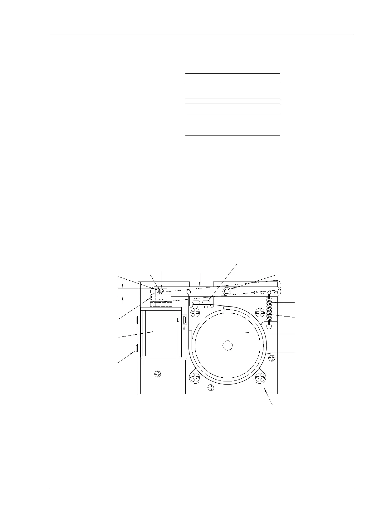
9. If the readings are low in both directions, detach the brake spring from the
anchor hole on the brake lever and attach the spring to the next hole located
further away from the brake solenoid (refer to Figure 6-2).
10. If the readings are high in both directions, move the spring anchor point
closer to the brake solenoid.
11. After the spring anchor point is moved, re-check the brake torque.
12. Repeat the brake torque adjustment on the take-up reel.
NOTE: When measuring the brake torque of the take-up side, the torque of
the clockwise rotation is larger than the counterclockwise torque.
TWO CROSS-RESESSED SCREWS
RETAINING RING B
SOLENOID PIN BRAKE ARM RETAINING RING A
BRAKE
SPRING
BRAKE ASSEMBLY
MOUNTING SCREW
BRAKE
DRUM
BRAKE
BAND
BRAKE GUIDEBRAKE BAND GUIDE
PLUNGER
STROKE
0.2±0.02 inch
(5±0.5mm)
CUSHION
BRAKE
SOLENOID
TWO HEX SOCKET
HEAD SCREWS