Introduction
8 900-0054-01-00 Rev A
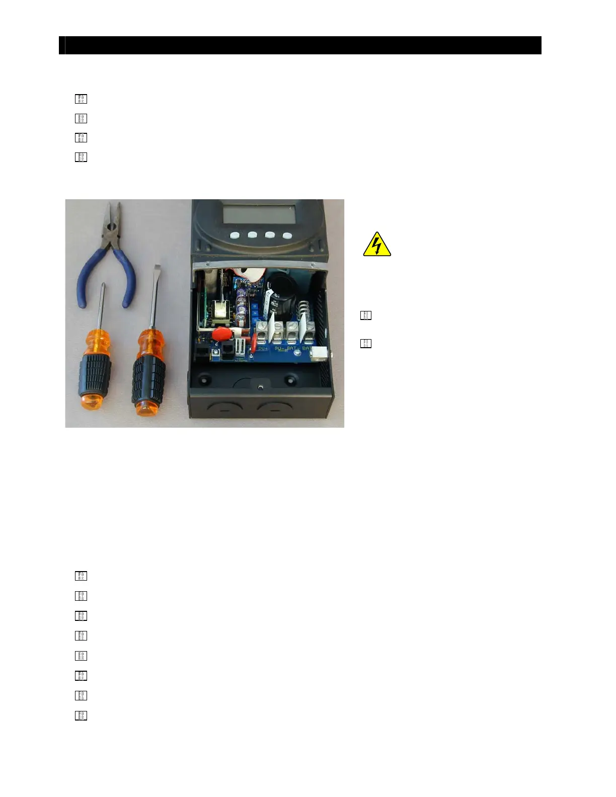
Tools Requi r ed
Phillips Screwdriver
Fl at Scr ew d ri ver
Long-Nose Pliers
Diagonal Wire Cutters (not shown)
Preliminary
Figure 2 Charge Controller “At Rest”
NOTE
: As many as 33 screws may be removed during t his procedure. Be sure t o put them aside in the
order they are removed.
Summary List of Instructions
The following is a list of the instructions that are included in this document.
For instructions for
Removing the FLEXmax 80 Fan Cable
, see page 9.
For instructions for
Di sassembl i ng t he Chassi s
, st art on page 10.
For instructions for
Removing the Heat Sink
, see page 11.
For instructions for
Rem o v i n g t he FET Bar
, see page 12
For instructions for
Sep ar at i n g t h e Heat Si n k f r o m t h e Po w er Bo ar d
, see page 14.
For instructions for
Replacing the Fan and Button Board
, see page 17.
For instructions for
Replacing the Control Board and Power Board
, see page 23.
For instructions for
Reassembling the Charge Controller
, see page 27.
WARNING: Shock Hazar d
If the unit has been in use, power can
still be present even after the unit has
been disconnect ed.
Remove all electrical connections
from t he FLEXmax cont roller.
Allow the controller t o “rest” for
approximately ten minutes to fully
discharge the PV input capacit ors.