Fan and Button Board
22 900-0054-01-00 Rev A
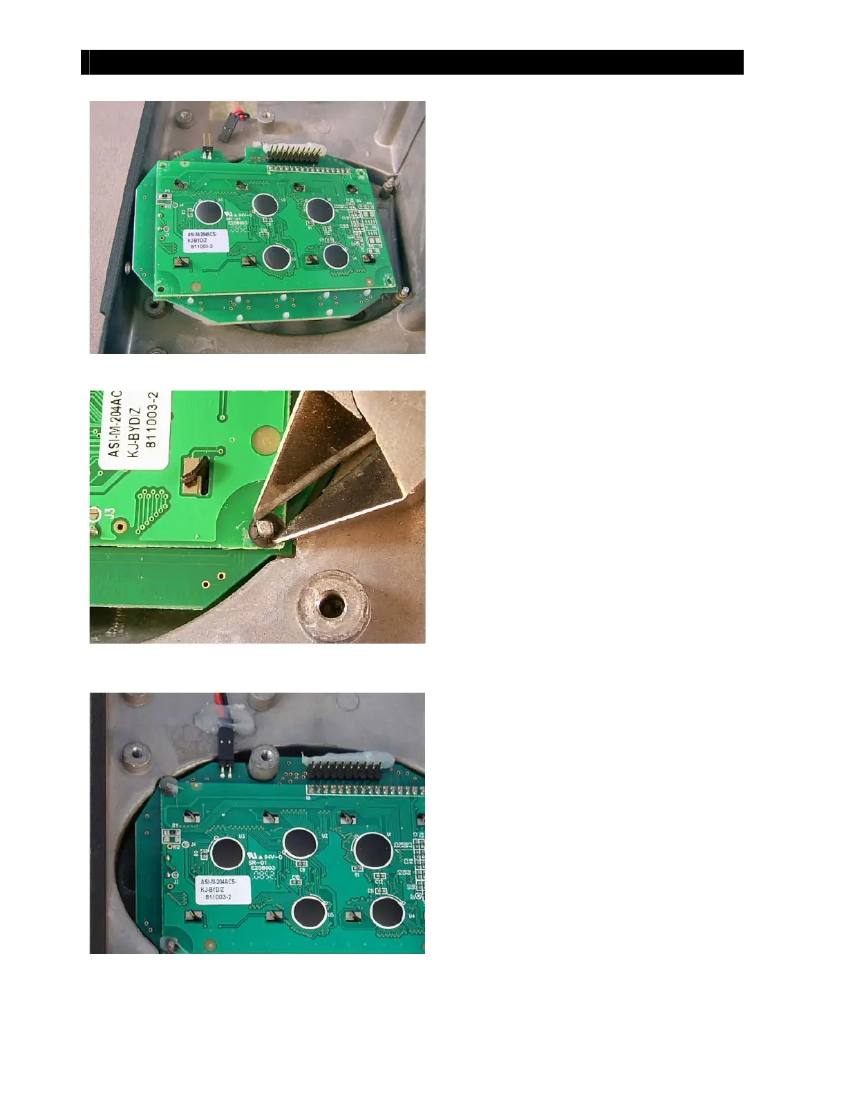
Figure 29 Inserting the New Button Board
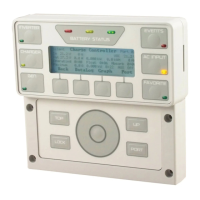
Figure 30 Inserting New Push-nut
Fi gu r e 31 Reco n n ect i ng t h e Fan
5. Insert the replacement board and align
it wit h the four pegs.
6. Lay a replacement push-nut over each peg.
The push-nuts are not flat. Make certain to
place t hem so t hat t he edges are lower and
the convex center is higher.
7. Using t he wire cut t ers or long-nose pliers,
press along both sides of the push-nut so
that it is driven onto the peg. Continue
pressing until the push-nut is firmly against
t he button board.
8. Repeat wit h t he ot her three push-nut s
and pegs.
9. Reattach the connector for the fan.
10. If possible, reapply silicone sealant to
secure t he fan connector and t he four
push-nuts.
Proceed t o the next sect ion if you need t o
replace the cont rol board or power board.
If not , proceed t o page 27 to begin
reassembling the charge controller.