Control Board and Power Board
900-0054-01-00 Rev A 25
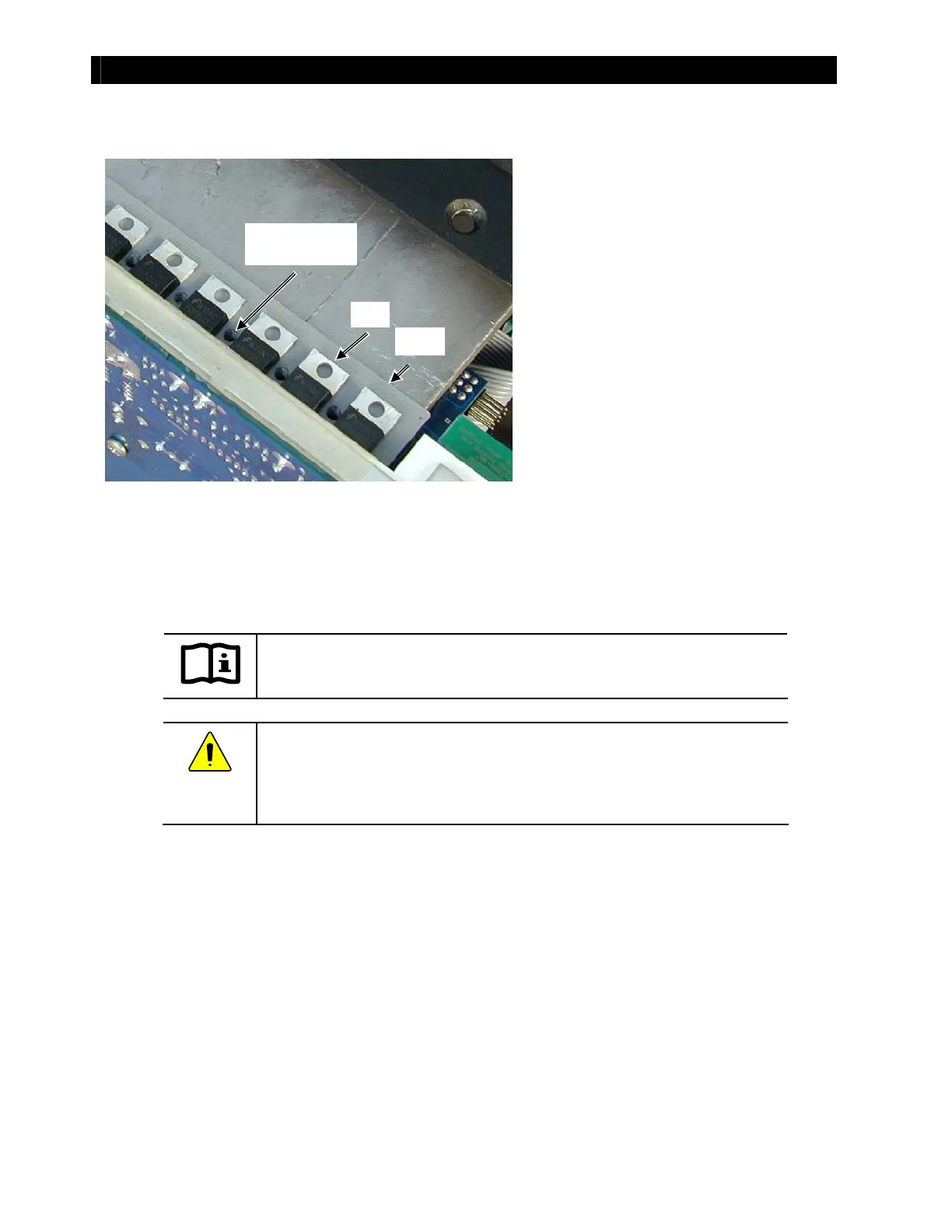
Fi g u r e 37 FETs an d Si l -Pad In su l at or o n Heat Si n k
IMPORTANT:
Make cert ain t he new Sil-Pad is lined up wit h t he screw holes on the heat sink.
CAUTION: Eq u i p men t Fai l u r e
Always replace t he Sil-Pad even if t he old Sil-Pad appears usable. It could easily
have been damaged when removing the heat sink from the power board. Even
a pin-sized hole can lead t o catast rophic board failure.
FET
Sil-Pad
6. Using the replacement t hat came with
t he new board, replace t he gray Sil-Pad
insulator on the heat sink.
Scr ew Ho l e o n
the Heat Sink