900-0054-01-00 Rev A 17
Fan an d Bu t t on Boar d
Replacing the FLEXmax 60 Fan
Disassemble the controller as described on page 9 through page 16.
Remo v i n g t h e Fan
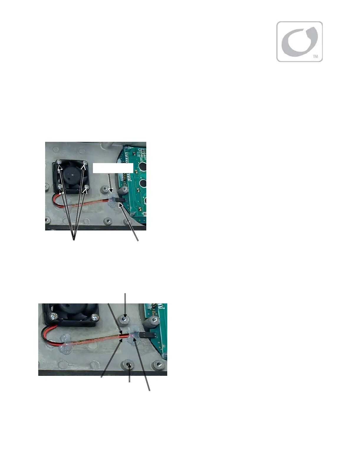
Fi gur e 19 Fan Removal
Rep l aci n g t h e Fan
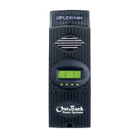
Fi gur e 20 Fan Rep l acemen t
If no ot her repairs are necessary, see t he reassembly instruct ions on page 27. After reassembly, return to
page 18 for testing procedures.
To remove the fan:
1.
Disconnect the connector from the LCD. The
connector may have a dollop of silicone sealant to
ensure a firm connection. This should be peeled or
pulled off.
2.
Remove t he four screws holding t he fan in place.
Fan Scr ews (x 4)
Fan Connector
NOTE:
The ribbon cable is shown disconnect ed
in this illustration for convenience only.
Silicone Sealant
Silicone Sealant
Black Wi r e
Red Wi r e
Scr ew Po st
Scr ew Po st
To r ep l ace t h e f an :
1. Insert the new fan aligning the mounting holes to
the heat sink.
2. Align t he connect or so that the red wire of the
connect or lines up wit h the posit ive (+) pin and the
black wire with t he negative (-) pin as shown in
Figure 20. Posit ion the wires between the
screw p ost s.
3. Plug in the connector.
4. Tight en t he screws so t he fan is snug against t he
heat sink.
5. Reapply silicone sealant to secure the connector
(if possible).