900-0054-01-00 Rev A 7
Introduction
Overview
This step-by-step guide illustrates the replacement of the Control Board, Power Board and Button Board
for all FLEXmax Series Charge Controllers. It also illustrates t he replacement of t he Fan for FLEXmax 60
charge cont rollers only. It does not cover replacing t he fan in a FLEXmax 80 charge controller.
A static-safeguarded workspace should be used to preserve the FLEXmax controller’s static-sensitive
component s during t he removal and inst allat ion procedure. See t he sect ion t it led Equipment Safet y on
page 3 for more specific instruct ions.
Please review this guide and familiarize yourself with the complete repair procedure. OutBack technical
support is also available at
(360) 618-4363
or
support@outbackpower.com
.
CAUTION: Eq u i p m en t Dam ag e
This procedure involves sensitive electronics which must be handled gently
and carefully during removal and installation. Applying excess force can
damage the components and cause the FLEXmax controller to malfunction.
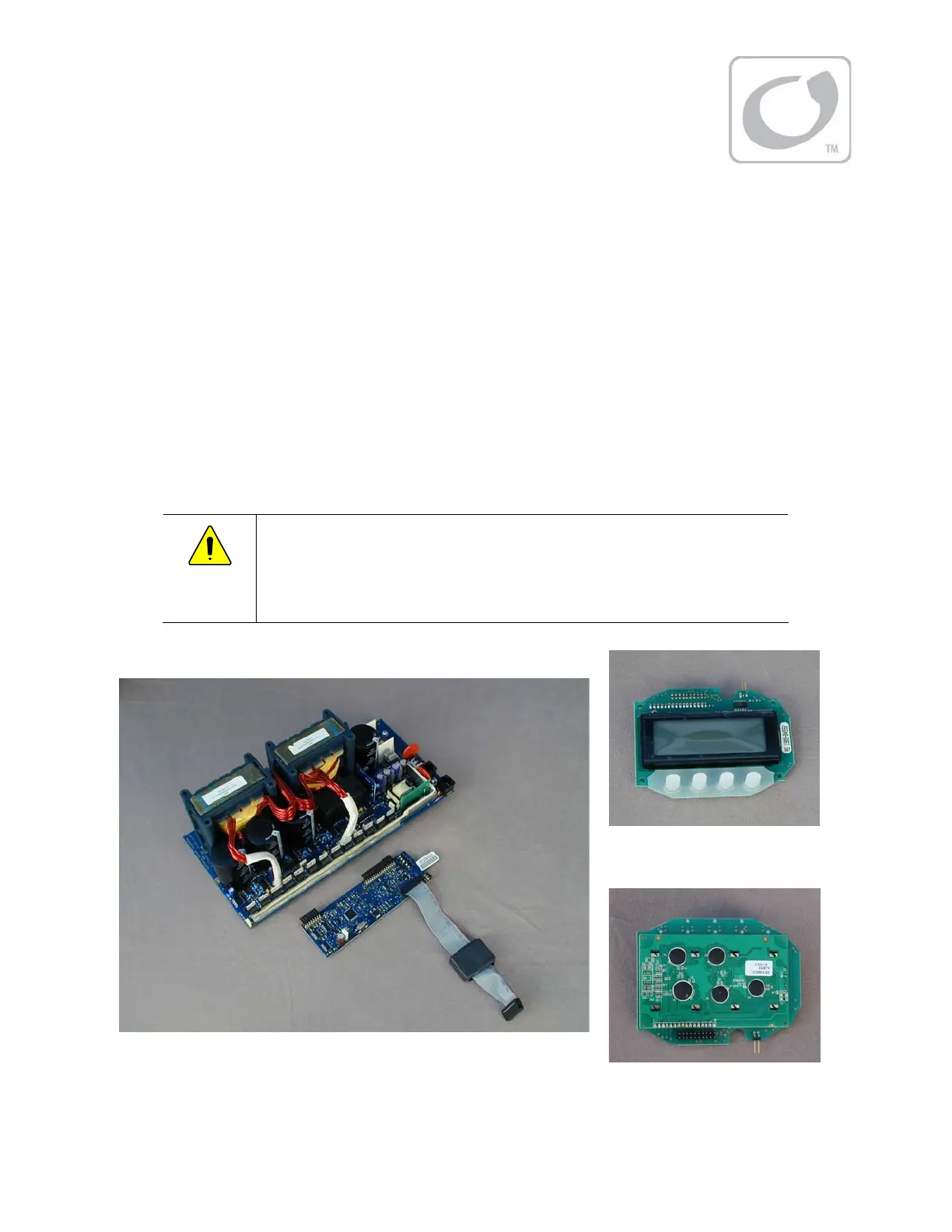
Figure 1 Components
Pow er Boar d
Control Board
But t on Boar d
(front )
Pow er Boar d
(back)