Fan and Button Board
18 900-0054-01-00 Rev A
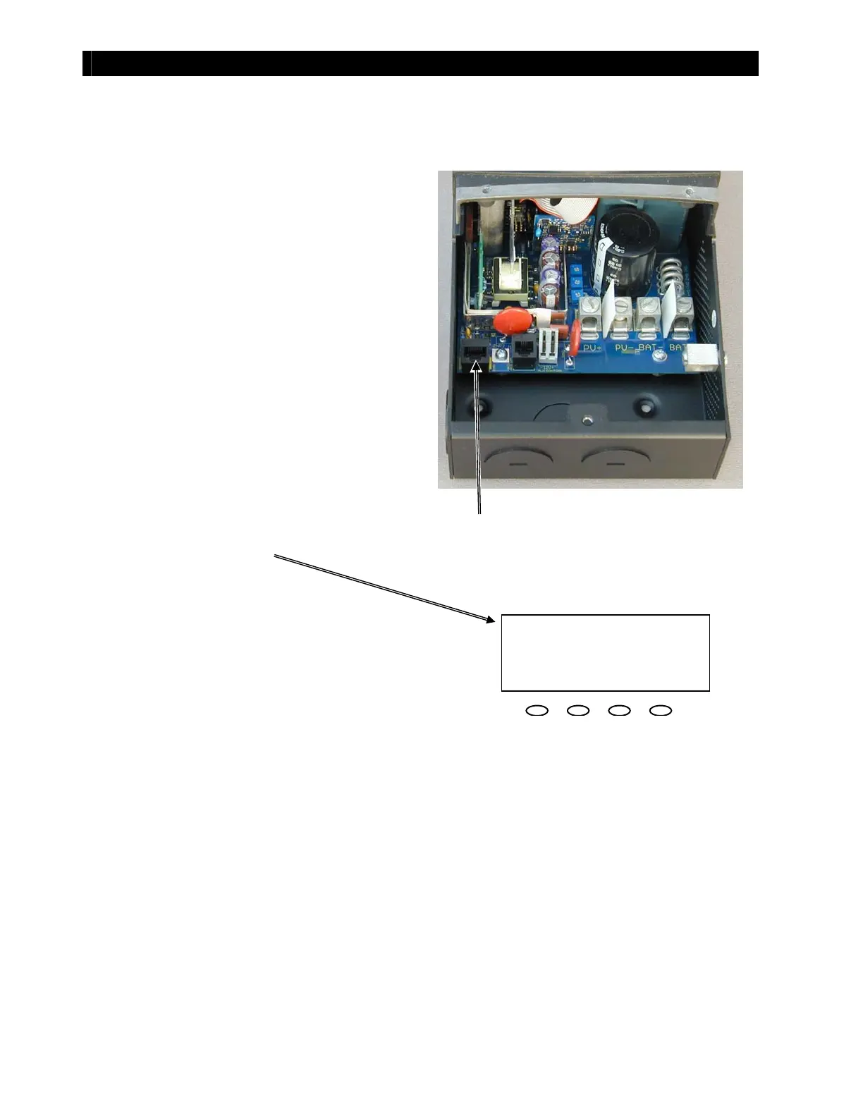
Fan Test Pr ocedur es
Test t he fan using t he following procedures:.
Figure 21 Fan Test Procedure
You may now apply PV input to the FLEXmax Charge Controller to resume charging.
3. Check t he LCD. The operat ional mode on
the FLEXmax screen should change from
“Sleeping” t o “BatTmpErr”. The fan will
begin running.
1. Remove the Remote Temperature
Sensor (RTS) jack from t he port , if
present.
2. Insert a flat screwdriver inside the RTS
port. Gently press the screwdriver tip
against all the pins at once. This will
create a false signal t hat will t urn t he
fan on.
4. Once the fan operation has been verified,
remove t he screwdriver from t he RTS port
and reconnect t he RTS, if available.
IN 005 V OUT 25.0 V
00.0 A 00.0 A
Watts 0000 AuxOff
kWHrs 00.0 BatTm
Err
LCD Display
RTS Po r t