Reassembly
900-0054-01-00 Rev A 29
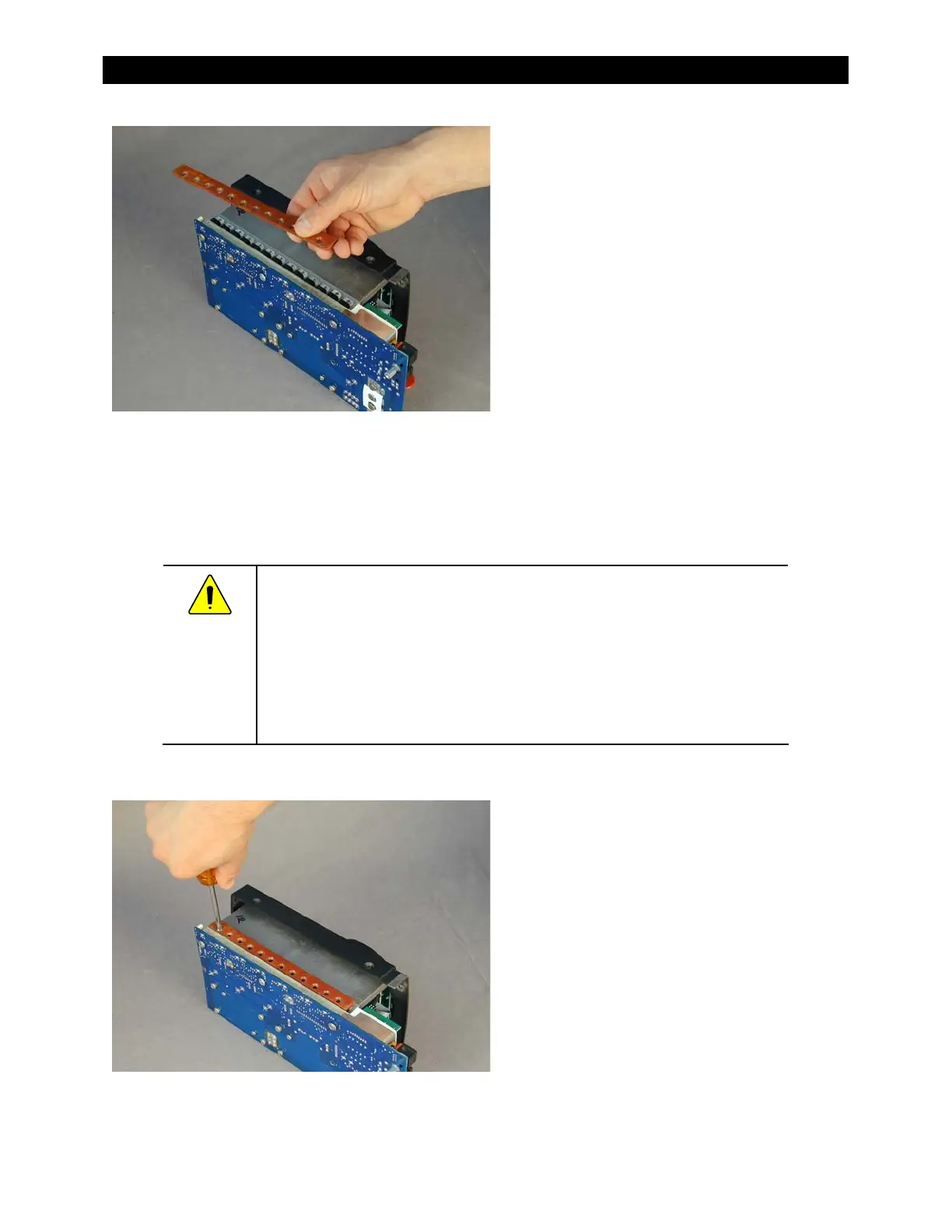
Fi g u r e 43 Al i g n i n g FETs and Inst al l i n g t he FET Bar
CAUTION: Eq u i p men t Dam ag e
Always replace t he Sil-Pad even if t he old Sil-Pad appears usable. It
could easily have been damaged when removing t he heat sink from t he
power board. Even a pin-sized hole can lead t o cat ast rophic board
failure.
Make sure the new Sil-Pad is lined up wit h t he screw holes on t he
heat sink.
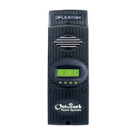
Figure 44 Installing FET Bar Screws
6. Set t he unit on it s side wit h t he FETs in
between the screw holes on the
heat sink.
If t hey do not line up, move t he t abs on
the FETs to align t hem between t he
screw holes. The alignment of the FETs
between the screw holes protects them
from damage when reinstalling the FET
mounting bar and screws.
7. If you are reassembling the unit
(following fan replacement) and have
not already performed t his step: using
the replacement that came with the fan,
replace the gray Sil-Pad insulator on the
heat sink. Refer t o t he illustration on
page 27 if necessary.
8. Place the FET mounting bar on
the FETs.
9. Install the FET bar screws and
tighten.