147
5. System settings
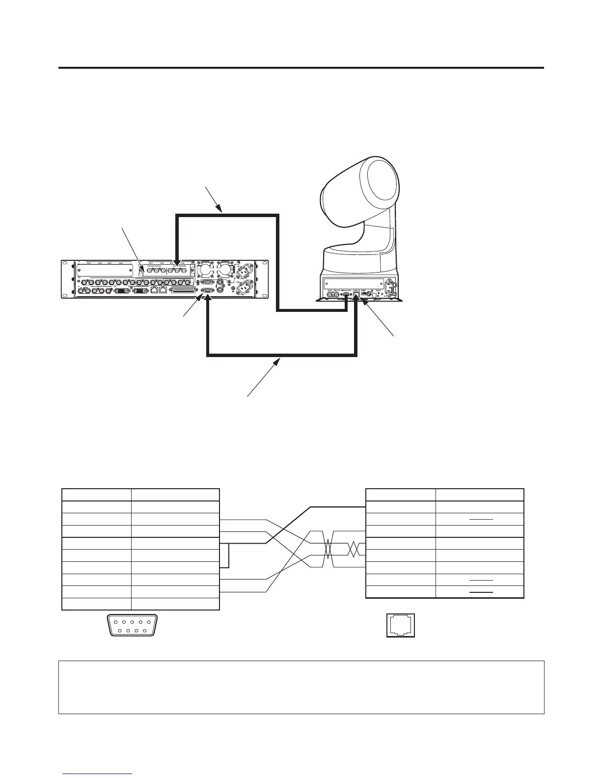
Example of connections (when the unit and a pan-tilt head are connected)
Pan-tilt heads that can be connected: AW-HE100E, AW-PH400E, AW-PH405E, AW-PH360L
Connections for AW-HE100E, AW-PH405E or AW-PH360L
SIGNAL
GND
REF
EDITOR
COM
TALLY/GPI
PANELLAN
234 56
321456789 10 11 12 13 14 15 16 C/C
U/C
1
SDI OUTPUTS
SDI INPUTS
DVI-D OUTPUTS
IN/OUT B2IN/OUT B1
SLOT B
IN/OUT A2IN/OUT A1
SLOT A
Pr
PbY
Pr
PbY
ANALOG INPUTS
CONTROLLER connector
Cable length: Max. 200 m
Twisted pair cable (AWG24)
AV-HS450E
AW-HE100E
Analogue component signals
(For the connection specifi cations, refer to the
operating instructions of the AW-HE100E.)
Analogue Input Board
COM connector
<Connection specifications>
1 FRAME GND
2 RXD –
3 TXD +
4 GND
5
6 GND
7 RXD +
8 TXD –
9 FRAME GND
NC
1
2
3
4
5
6
7
8
RXD –
GND
TXD –
RXD +
TXD +
COM
CONTROLLER
(CONTROL IN IP/RP)
12345
9 876
1.......8
Pin No. Signal Pin No. Signal
AV-HS450E
AW-HE100E, AW-PH405E, AW-PH360L
: Twisted pair cable
When the AW-HE100E is to be connected to the unit, select a setting which will enable operations to be
controlled by the controller in the “Controller” item of the AW-HE100E’s pan-tilt head unit setting menu ( Pan
Tilt Head Setting ).
For further details, refer to the operating instructions of the AW-HE100E.
 Loading...