Electrical Adjustment for AJ-BS900HP & CA900HP
ELE-2
3. BS POWER, BS AUDIO
3-1. Power Voltage Adjustment
BOARD
BS POWER, BS AUDIO
TP
VFK
1671
A10 pin, GND : A78pin
ADJ.
VR1 [V ADJ] (BS POWER UNIT)
INPUT
------
M. EQ
D.V.M
SPEC.
5.0V +/- 0.05V
1. Extend BS AUDIO Board with Extension Board
(VFK1671).
2. Connect D.V.M to A10pin on the VFK1671 and then
adjust VR1 so that voltage is within the specification.
3-2. OSC Frequency Adjustment
BOARD
BS AUDIO
TP
VFK
1671
B58 pin
ADJ.
X1 [14MHz VCO], VR18 [SC LVL]
INPUT
------
M. EQ
Frequency counter, Oscilloscope
SPEC.
A = 3.579545MHz +/- 5Hz
B = 1.0Vp-p +/- 1% (0.01V)
1. Extend BS AUDIO Board with Extension Board
(VFK1671).
2. Connect Frequency counter to B58pin on the
VFK1671 and then adjust X1 so that the Frequency
A is within the specification.
3. Connect Oscilloscope to B58pin on the VFK1671
and then adjust VR18 so that the signal level B is
within the specification.
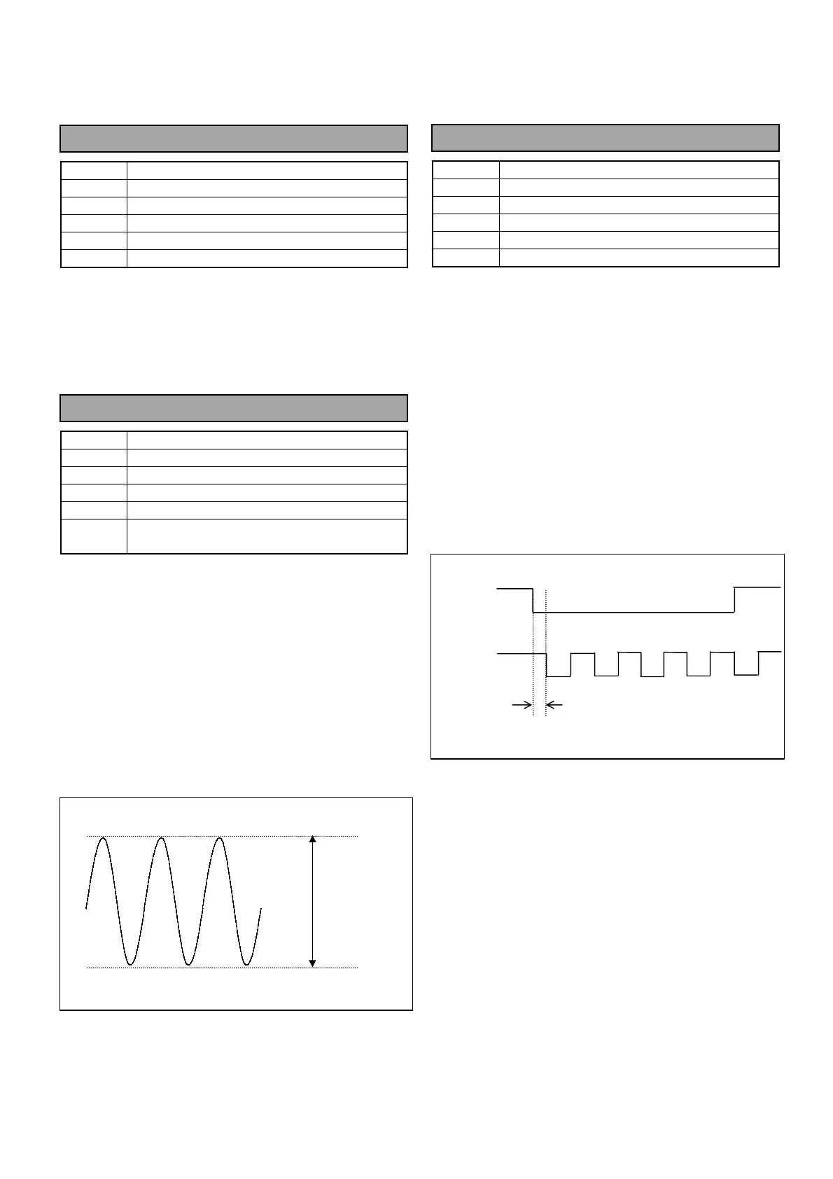
3-3. 27MHz Frequency adjustment
BOARD
BS AUDIO
TP
TP3 [HD], TP4 [CLK13.5M]
ADJ.
VR16 [27M
∅
]
INPUT
Black Burst signal (or Color bars)
M. EQ
Oscilloscope
SPEC.
A = 9nS +/- 1nS
1. Connect Oscilloscope to TP3 and TP4.
2. Supply Black Burst signal (or Color bar signal) to
GENLOCK IN connector on the rear panel of AJ-
BS900H.
3. Check the “GENLOCK” indicator on the front panel
of AJ-BS900H is lighting.
4. Adjust VR16 so that signal timing between TP3 and
TP4 (A) is within the specification.
5. Set AJ-BS900H to internal lock mode (no signal
input from GENLOCK IN Connector) and then
confirm the timing A is within the specification.
TP3 [HD]
TP4 [CLK]
A
B
 Loading...