Electrical Adjustment for AJ-BS900HP & CA900HP
ELE-5
4-4. I/Q Adjustment
BOARD
BS DIGITAL
TP
ENC1 OUT
ADJ.
VR17 [I-GAIN], VC1
VR16[BURST PHASE], VR20 [BURST LVL]
INPUT
AJ-BS900H Internal Color bar signal
M. EQ
Vector Scope (With 75
Ω
termination)
Oscilloscope
SPEC.
As shown below
1. Set SW2 on the BS DIGITAL Board as shown
below.
SW2-2 [Q-ON] : ON
SW2-3 [I-ON] : OFF
2. Connect Vector scope to ENC1 OUT connector and
then adjust “Phase knob” and “Variable knob” on
the Vector scope so that the all Dots are on the Q
axis, straight.
3. Set SW2 on the BS DIGITAL Board as shown
below.
SW2-2 [Q-ON] : OFF
SW2-3 [I-ON] : ON
4. Connect Vector scope to ENC1 OUT connector
and then adjust VC1 and VR17 so that the all dots
are on the scale of I axis.
5. Set SW2 on the BS DIGITAL Board as shown
below. And confirm the Vector scope’s picture that
all dots are within each Inner box.
SW2-2 [Q-ON] : OFF
SW2-3 [I-ON] : OFF
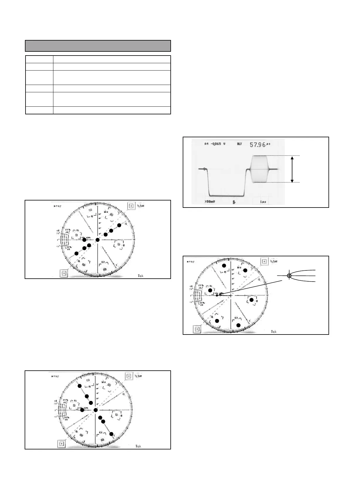
6. Connect Oscilloscope to ENC1 OUT connector and
then adjust VR20 so that the Color burst level A is
40 IRE (286mV) +/- 1%.
7. Connect Vector scope to ENC1 OUT connector and
then adjust VR16 so that the Color burst phase B
meet to the scale on the Vector scope.
75%
A
 Loading...