Electrical Adjustment for AJ-BS900HEN & CA900HEN
ELE-15
7. BS DIGITAL
7-1. Carrier Balance Adjustment
BOARD
BS DIGITAL
TP
ENC1 OUT
ADJ.
VR21 [BAL2], VR22 [B-Y BLK BAL]
VR18 [BAL1], VR19 [R-Y BLK BAL]
INPUT
AJ-BS900H Internal Color bar signal : ON
M. EQ
Vector scope (with 75
Ω
termination), 5x mode
SPEC.
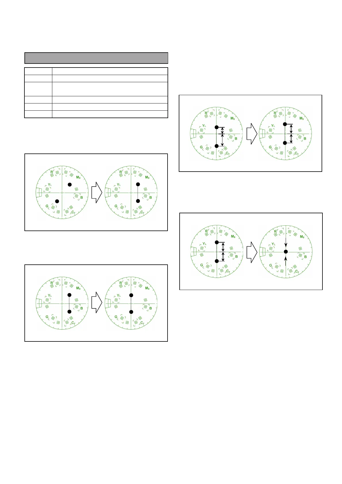
As shown below
1. Connect Vector scope to ENC OUT1 and then
adjust VR21 so that the two vector dots are in
parallel with V axis on the scope.
2. Adjust VR22 so that the two vector dots meet to V
axis on the scope.
3. Adjust VR18 so that the two vector dots become
equal distance (A = B) from center position on V
axis of the scope.
4. Adjust VR19 so that the two vector dots come to
center position of the scope.
A
B
A
B
A
B




 To Next Page