Electrical Adjustment for AJ-BS900HP & CA900HP
ELE-7
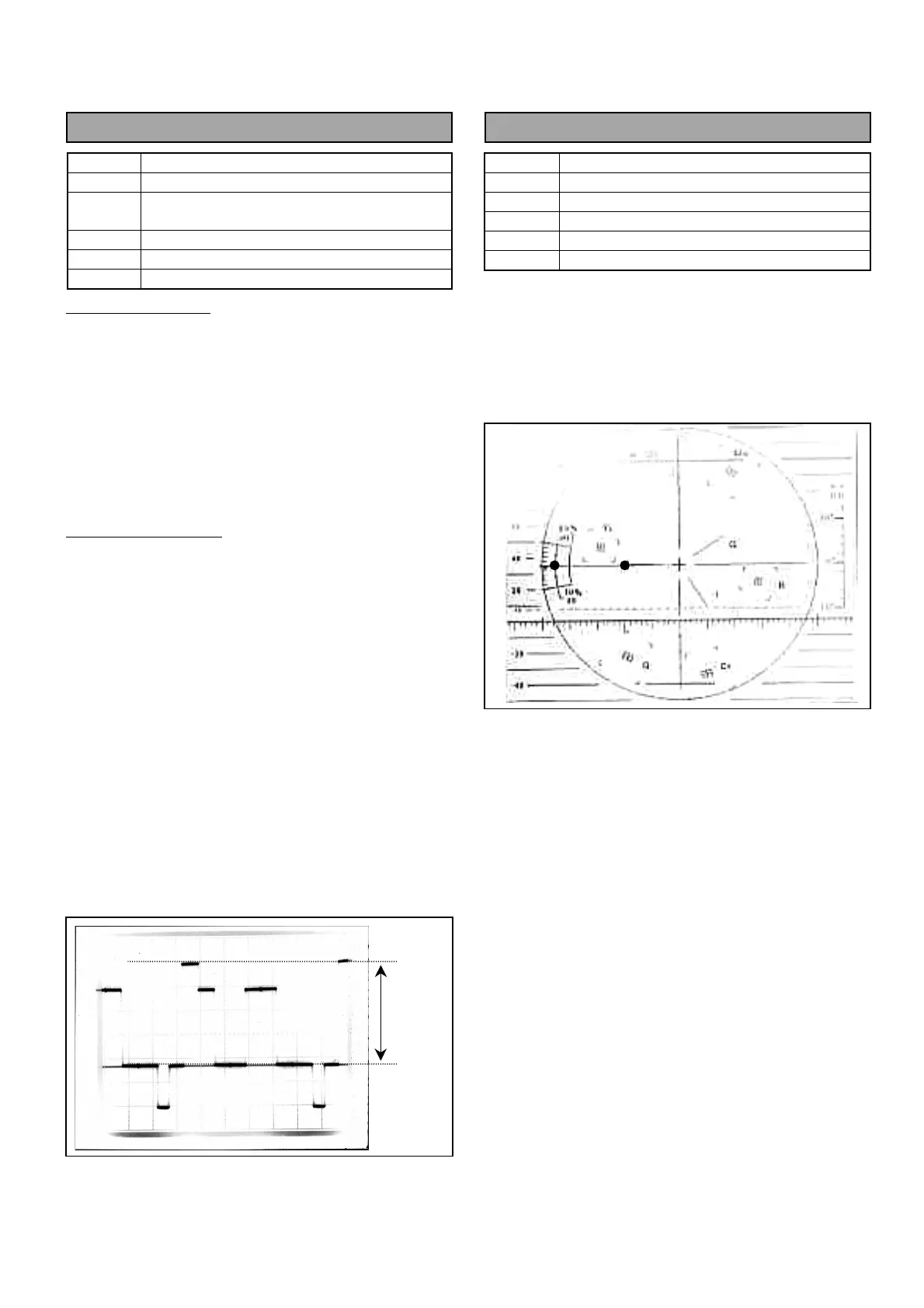
4-7. PIX, WFM Output Level Adj.
BOARD
BS DIGITAL
TP
PIX OUT, WFM OUT
ADJ.
VR1 [PIX GAIN], VR2 [WFM GAIN]
VR15 [MON ENC GAIN]
INPUT
AJ-BS900H Internal Color bar signal
M. EQ
Oscilloscope (With 75
Ω
termination)
SPEC.
A = 714mVp-p +/- 1%
Setting for PIX OUT
1. Set MON SEL SW on the front panel of AJ-
BS900H as shown below.
MON SEL : SEQ
2. Connect Oscilloscope to PIX OUT connector and
then adjust VR1 so that the signal level A is within
the specification.
Setting for WFM OUT
3. Set MON SEL SW on the front panel of AJ-
BS900H as shown below.
MON SEL : SEQ
4. Connect Oscilloscope to WFM OUT connector and
then adjust VR2 so that the signal level A is within
the specification.
5. Set MON SEL SW on the front panel of AJ-
BS900H as shown below.
MON SEL : ENC
6. Connect Oscilloscope to WFM OUT connector and
then adjust VR15 so that the signal level A is
within the specification.
4-8. SCH Adjustment
BOARD
BS AUDIO
TP
ENC1 OUT
ADJ.
VR17 [SCH]
INPUT
------
M. EQ
SCH Meter (With 75
Ω
termination)
SPEC.
SCH = 0
°
+/- 10
°
1. Set Genlock mode of AJ-BS900H to Internal (No
signal input from GENLOCK IN Connector).
2. Connect SCH Meter to ENC1 OUT connector and
then adjust VR17 so that the SCH is within the
specification.
A
 Loading...