Electrical Adjustment for AJ-BS900HEN & CA900HEN
ELE-13
6. BS POWER, BS AUDIO
6-1. Power Voltage Adjustment
BOARD
BS POWER, BS AUDIO
TP
VFK
1671
A10 pin, GND : A78pin
ADJ.
VR1 [V ADJ] (BS POWER UNIT)
INPUT
------
M. EQ
D.V.M
SPEC.
5.0V +/- 0.05V
1. Extend BS AUDIO Board with Extension Board
(VFK1671).
2. Connect D.V.M to A10pin on the VFK1671 and then
adjust VR1 so that voltage is within the
specification.
6-2. OSC Frequency Adjustment
BOARD
BS AUDIO
TP
VFK1671 : B58 pin
ADJ.
X1, VR16 [27
∅
], VR18 [SC LVL]
INPUT
------
M. EQ
Frequency counter, Oscilloscope
SPEC.
A = 4.43361875MHz +/- 5Hz
B = 1.0Vp-p +/- 1% (0.01V)
1. Set VR16 to center position.
2. Extend BS AUDIO Board with Extension Board
(VFK1671).
3. Connect Frequency counter to B58pin on the
VFK1671 and then adjust X1 so that the frequency
A is within the specification.
4. Connect Oscilloscope to B58pin on the VFK1671
and then adjust VR18 so that the signal level B is
within the specification.
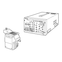
6-3. RGB Output Level Adjustment
BOARD
BS DIGITAL
TP
Y/G OUT, PR/R OUT, PB/B OUT
ADJ.
VR5 [Y/G GAIN], VR6 [PR/R GAIN],
VR7 [PB/B GAIN] (with 75
Ω
termination)
INPUT
AJ-BS900H Internal Color bar signal : ON
M. EQ
Oscilloscope
SPEC.
As shown below
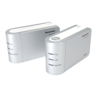
1. Set SW2-1pin on the BS DIGITAL Board to OFF.
(Y/C → R, G, B output mode)
2. Connect Oscilloscope to Y/G OUT and then adjust
VR5 so that the signal level A is 700mV +/- 1%.
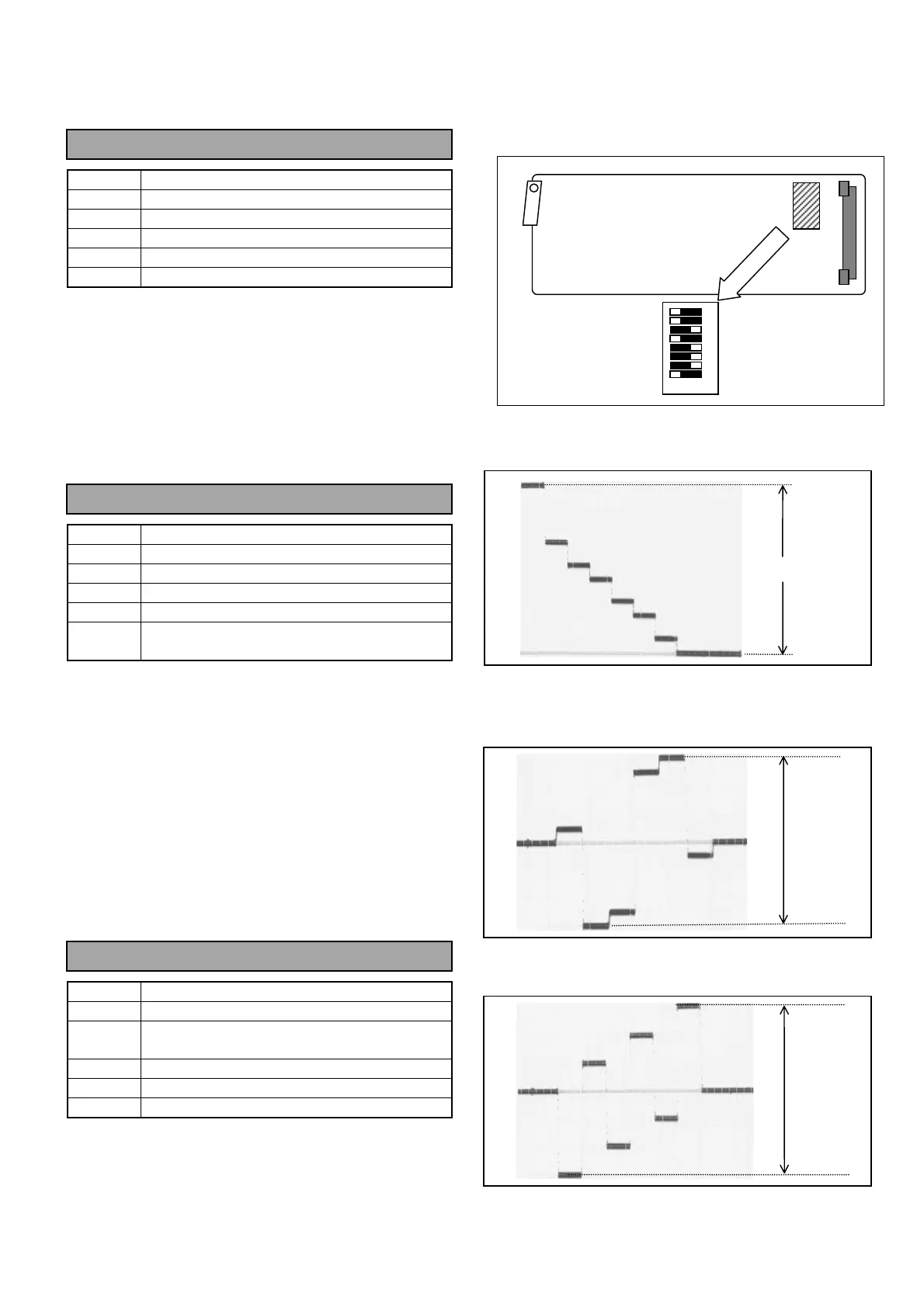
3. Connect Oscilloscope to PR/R OUT and then
adjust VR6 so that the signal level B is 525mV +/-
1%.
4. Connect Oscilloscope to PB/B OUT and then adjust
VR7 so that the signal level C is 525mV +/- 1%.
ON OFF
8
7
6
5
4
3
2
1
SW2
BS DIGITAL BOARD
A
B
C
 Loading...