Electrical Adjustment for AJ-BS900HP & CA900HP
ELE-12
5. CAM POWER, CAM DIGITAL
5-1. Power Voltage Adjustment
BOARD
CAM POWER
TP
VFK
1670
A10pin, A13pin, A16pin, A20pin,
GND : A78pin
ADJ.
VR1 [V ADJ]
INPUT
------
M. EQ
D.V.M
SPEC.
As shown below
1.
Extend CAM POWER Board with VFK1670.
2.
Connect D.V.M. to following test-points and then
adjust VR1 so that the each voltage is within the
specification.
TP Specification
A10pin 5.00V +/- 0.15V
A13pin 3.30V +/- 0.10V
A16pin 12.00V +/- 0.40V
A20pin -5.60V +/- 0.17V
5-2. Video Level Adjustment
BOARD
CAM DIGITAL
TP
AJ-BS900H : Y/G, PR/R, PB/B OUT
ADJ.
VR1 [Y/G GAIN], VR2 [Y/G CLAMP DC]
VR3 [PR/R GAIN], VR4 [PR/R CLAMP DC]
VR5 [PB/B GAIN], VR6 [PB/B CLAMP DC]
INPUT
AJ-CA900H Internal Color bar signal
M. EQ
Oscilloscope
SPEC.
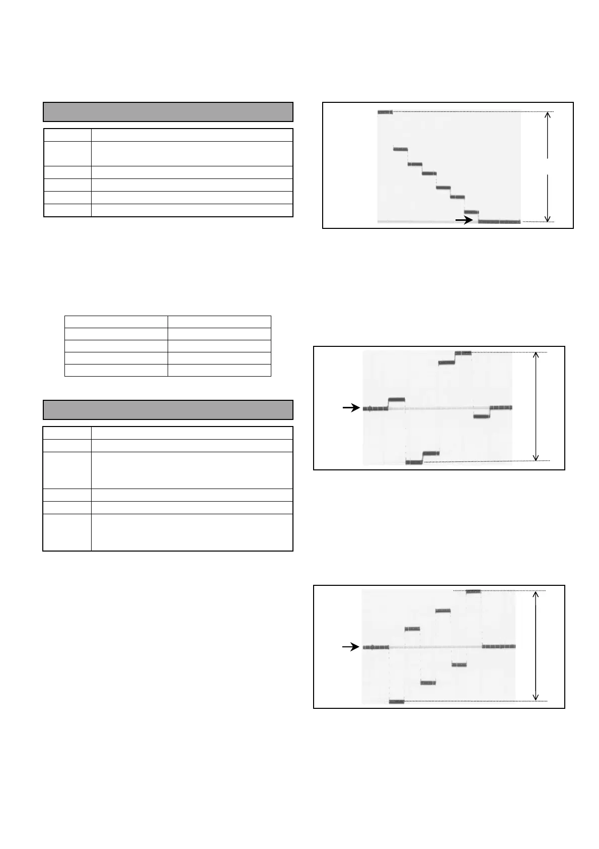
A = 714mV +/- 1%
B = 757mV +/- 1%
C = 757mV +/- 1%
1. Press “CALL” Button and “BARS” Button on front
panel of AJ-BS900H simultaneously. (AJ-CA900H
Internal color bar signal output mode.)
2. Connect Oscilloscope to Y/G OUT and then adjust
VR1 so that the signal level A is within the
specification.
3. Adjust VR2 so that the step D (“→
→→
→” portion)
become no step.
4. Connect Oscilloscope to PR/R OUT and then
adjust VR3 so that the signal level B is within the
specification.
5. Adjust VR4 so that the step E (“→
→→
→” portion)
become no step.
6. Connect Oscilloscope to PB/B OUT and then adjust
VR5 so that the signal level C is within the
specification.
7. Adjust VR6 so that the step F (“→
→→
→” portion)
become no step.
C
F
B
E
A
D



 To Next Page