Electrical Adjustment for AJ-BS900HP & CA900HP
ELE-6
4-5. ENC Output Level Adjustment
BOARD
BS DIGITAL
TP
ENC1 OUT, ENC2 OUT, ENC3 OUT,
ADJ.
VR8 [SYNC 1]
VR9, VR11, VR13 [CHROMA 1- 3]
VR10, VR12, VR14 [ENC 1- 3]
INPUT
AJ-BS900H Internal Color bar signal
M. EQ
Oscilloscope (With 75
Ω
termination)
SPEC.
As shown below
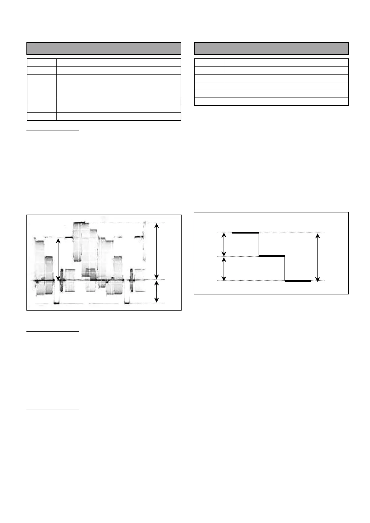
ENC1 Adjustment
1. Connect Oscilloscope to ENC1 OUT connector
and then adjust VR10 so that the signal level A is
714mV +/- 1%.
2. Adjust VR8 so that the Sync level B is 286mV +/-
1%.
3. Adjust VR9 so that the Chrominance level C meets
to luminance.
ENC2 Adjustment
4. Connect Oscilloscope to ENC2 OUT connector
and then adjust VR12 so that the signal level A is
714mV +/- 1%.
5. Adjust VR11 so that the Chrominance signal level
C meets to luminance.
ENC3 Adjustment
6. Connect Oscilloscope to ENC3 OUT connector
and then adjust VR14 so that the signal level A is
714mV +/- 1%.
7. Adjust VR13 so that the Chrominance signal level
C meets to luminance.
4-6. Stair Signal Level Adjustment
BOARD
BS DIGITAL
TP
VFK1671 A45 pin
ADJ.
VR3 [STAIR BAL], VR4 [STAIR GAIN]
INPUT
------
M. EQ
Oscilloscope (With 75
Ω
termination)
SPEC.
As shown below
1. Set MON SEL SW on the front panel of AJ-
BS900H as shown below.
MON SEL : SEQ
2. Extend BS DIGITAL Board with VFK1671.
3. Connect Oscilloscope to A45pin on VFK1671 and
then adjust VR4 so that the signal level is 10Vp-p.
4. Connect Oscilloscope to A45pin on VFK1671 and
then adjust VR3 and VR4 so that the step duty is
5Vp-p each.
10Vp-p
5Vp-p
5Vp-p
B
A
C
 Loading...