Electrical Adjustment for AJ-BS900HEN & CA900HEN
ELE-19
7-7. MIC Level Adjustment
BOARD
BS AUDIO
TP
AUDIO OUT 1CH, AUDIO OUT 2CH
ADJ.
VR10 [LVL], VR11 [LVL]
INPUT
As shown below
M. EQ
Audio Analyzer
SPEC.
CH1 = 0dBu +/- 1dB, CH2 = 0dBu +/- 1dB
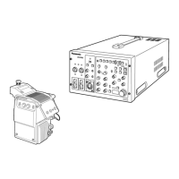
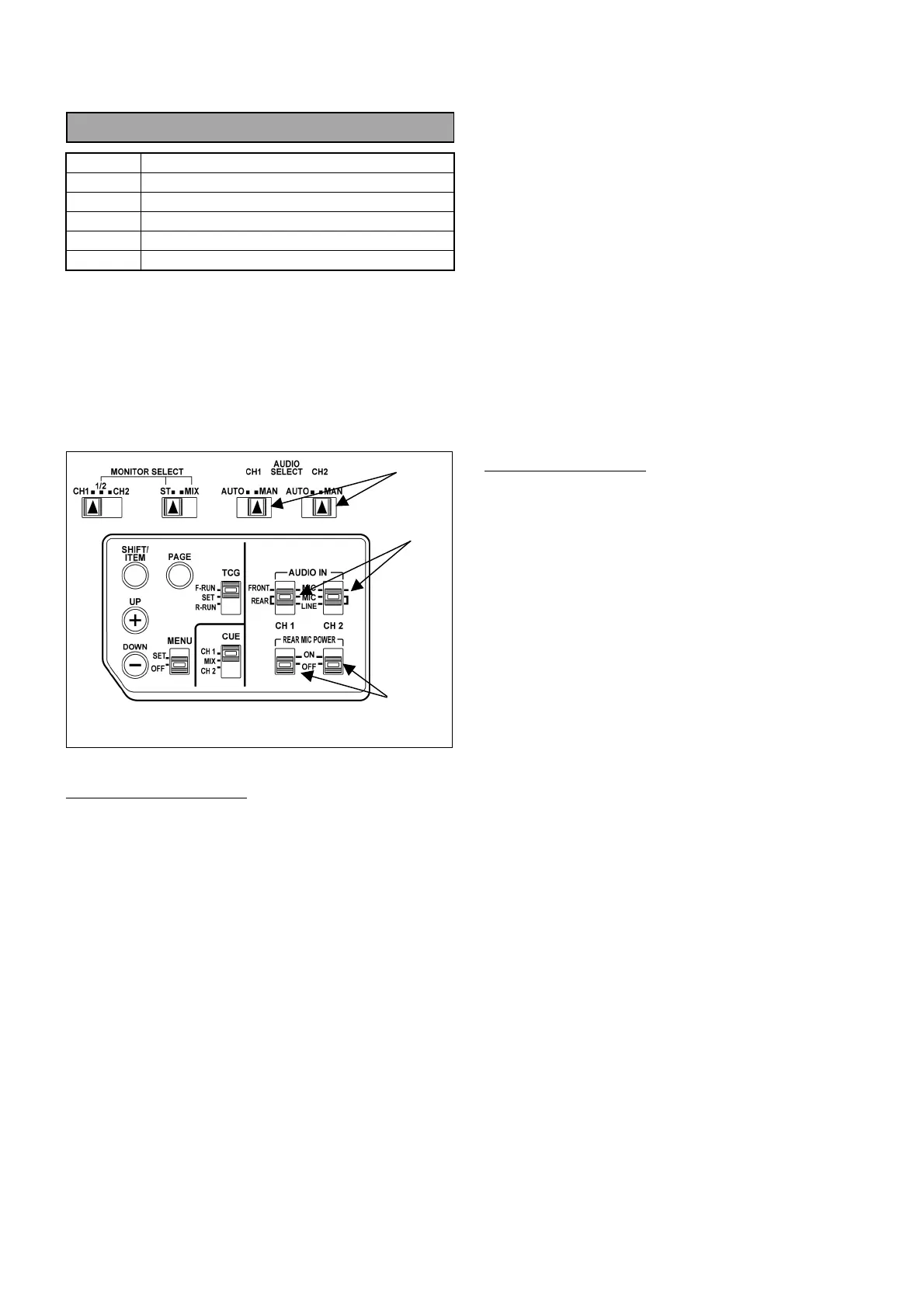
1. Set audio control switches on the DVCPRO
camcorder are shown below.
(1) AUDIO SELECT (CH1, CH2) : MAN
(2) AUDIO IN (CH1, CH2) : REAR MIC
(3) REAR MIC POWER (CH1, CH2) : OFF
(4) AUDIO CH FRONT VR : MAX.
Audio Analyzer’s setting
2. Connect AUDIO IN CH1 connector of camcorder
to OUTPUT A connector of audio analyzer.
3. Set output parameters of Audio analyzer as shown
below.
FUNCTION : OSC
FREQUENCY RANGE : X100
OUTPUT MODE : A
OUTPUT LEVEL : -60dBm
FREQUENCY : 1000Hz
LEVEL METER : 0dBm
LOAD : ON
4. Connect AUDIO OUT connector of camcorder to
INPUT A connector of audio analyzer.
5. Set input parameters of audio analyzer as shown
below.
FUNCTION : LM
INPUT IMPEDANCE : 10kΩ
FILTER : FLAT
LM/DM RANGE : AUTO
6. Adjust AUDIO LEVEL VR CH1 and CH2 so that
the output levels of camcorder (CH1 and CH2) are
within the specification.
MIC Level Adjustment
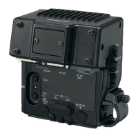
7. Connect AUDIO OUT CH1 connector of AJ-
BS900H to INPUT A connector of audio analyzer.
8. Adjust VR10 so that the AUDIO OUT level of CH1
is within the specification.
9. Connect AUDIO OUT CH2 connector of AJ-
BS900H to INPUT A connector of audio analyzer.
10. Adjust VR11 so that the AUDIO OUT level of CH1
is within the specification.
(1)
(2)
(3)
Side panel on camcorder