Electrical Adjustment for AJ-BS900HP & CA900HP
ELE-3
4. BS DIGITAL
4-1. RGB Output Level Adjustment
BOARD
BS DIGITAL
TP
Y/G OUT, PR/R OUT, PB/B OUT
ADJ.
VR5 [Y/G GAIN], VR6 [PR/R GAIN],
VR7 [PB/B GAIN] (With 75
Ω
Termination)
INPUT
AJ-BS900H Internal Color bar signal
M. EQ
Oscilloscope
SPEC.
A, B, C = 714mV +/- 1%
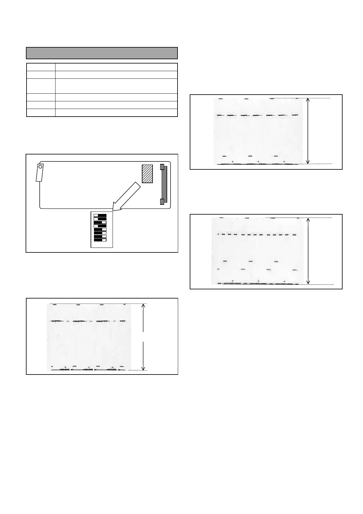
1. Set SW2-1pin on the BS DIGITAL Board to OFF.
(Y/C → R, G, B output mode)
2. Connect Oscilloscope to Y/G OUT connector and
then adjust VR5 so that the signal level A is within
the specification.
3. Connect Oscilloscope to PR/R OUT and then
adjust VR6 so that the signal level B is within the
specification.
4. Connect Oscilloscope to PB/B OUT and then adjust
VR7 so that the signal level C is within the
specification.
5. Set SW2-1pin to ON.
ON OFF
8
7
6
5
4
3
2
1
SW2
BS DIGITAL Board
A
B
C



 To Next Page