Electrical Adjustment for AJ-BS900HP & CA900HP
ELE-11
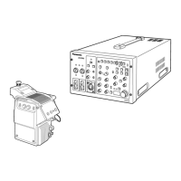
4-12. INCOM Level Adjustment
(BS900H
→
→→
→
CA900H)
BOARD
BS AUDIO, CAM INCOM
TP
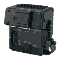
AJ-BS900H COMMUNICATION TERMINAL
6pin, 7pin
ADJ.
VR2 [2W] : BS AUDIO
VR4 [RTS LVL] : BS AUDIO
INPUT
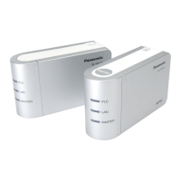
AJ-CA900H INCOM connector
M. EQ
Audio Analyzer
SPEC.
A = 0 +/- 1dBm
SW Setting
1. Set switches in AJ-CA900H and AJ-BS900H as
shown below.
SW Setting BOARD
SW1 [DM/CM] CM CAM INCOM
SW1 [ENG] 2W BS AUDIO
SW2 [ENG RTS LOAD] ON BS AUDIO
SW2 [DM/CM] CM BS INCOM
MIC SW ON CA900H side plate
Output Setting
2. Connect communication terminal 6 pin [ENG TO L
(H)] and 7pin [ENG TO L (C)] of AJ-BS900H to
OUTPUT A of audio analyzer.
3. Set output parameters of audio analyzer as shown
below.
FUNCTION : OSC
FREQUENCY RANGE : X100
OUTPUT MODE : A
OUTPUT LEVEL : 0dB
FREQUENCY : 1000Hz
LEVEL METER : 0dBm
LOAD : OFF
Input Setting
4. Connect INCOM connector 1pin [GND] and 2pin
[INCOM TALK] of AJ-CA900H to INPUT A
connector of audio analyzer.
5. Set input parameters of audio analyzer as shown
below.
FUNCTION : LM
INPUT IMPEDANCE : 10kΩ
FILTER : FLAT
LM/DM RANGE : AUTO
6. Adjust VR2 so that the audio level A is within the
specification.
7. Set switch on BS AUDIO BOARD as follows.
SW Setting BOARD
SW1 [ENG] RTS BS AUDIO
8. Adjust VR4 so that the audio level A is within the
specification.