Electrical Adjustment for AJ-BS900HP & CA900HP
ELE-8
4-9. MIC Level Adjustment
BOARD
BS AUDIO
TP
AUDIO OUT 1CH, AUDIO OUT 2CH
ADJ.
VR10 [LVL], VR11 [LVL]
INPUT
As shown below
M. EQ
Audio Analyzer
SPEC.
CH1 = 0dBu +/- 1dB, CH2 = 0dBu +/- 1dB
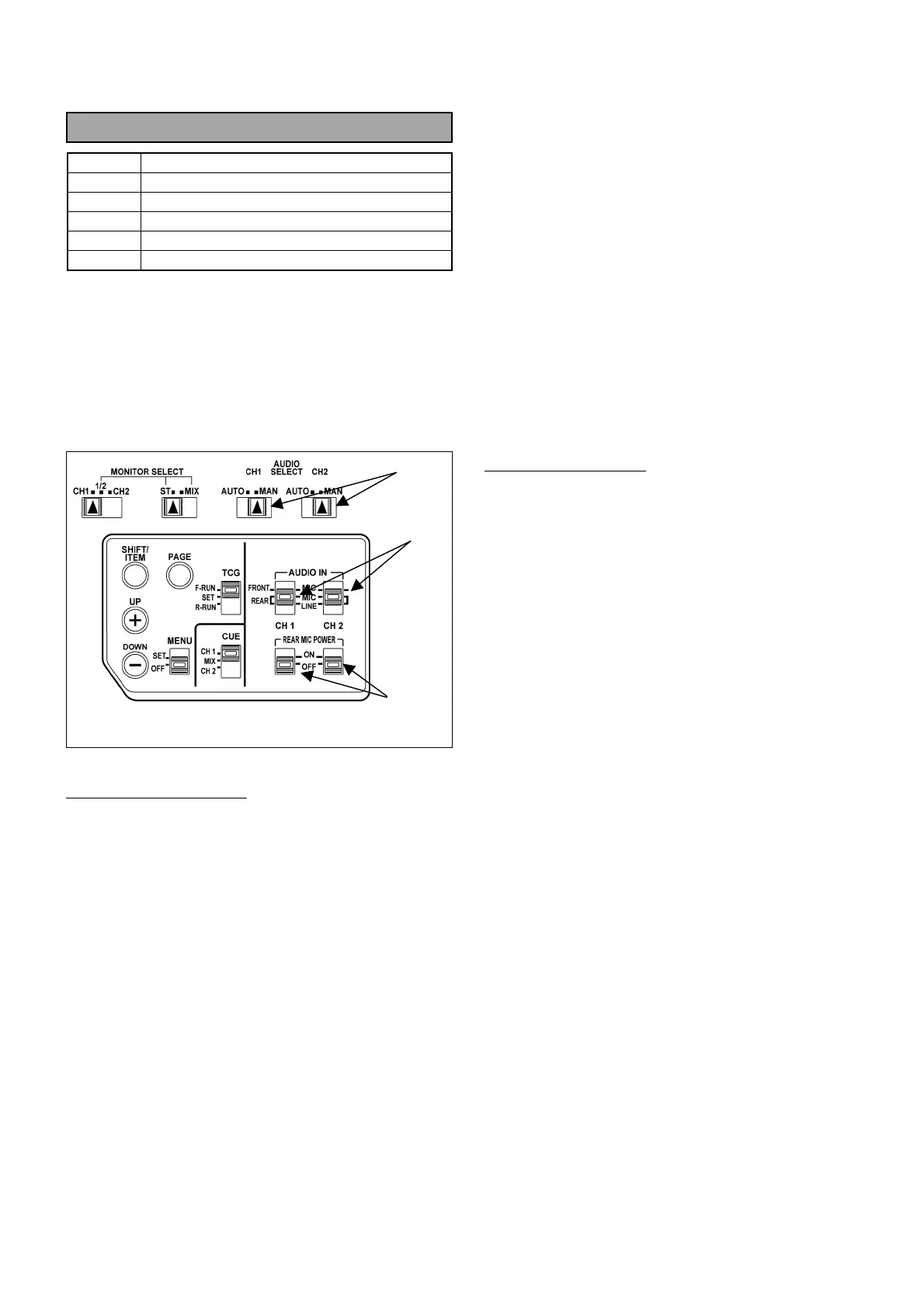
1. Set audio control switches on the DVCPRO
camcorder are shown below.
(1) AUDIO SELECT (CH1, CH2) : MAN
(2) AUDIO IN (CH1, CH2) : REAR MIC
(3) REAR MIC POWER (CH1, CH2) : OFF
(4) AUDIO CH FRONT VR : MAX.
Audio Analyzer’s setting
2. Connect AUDIO IN CH1 connector of camcorder
to OUTPUT A connector of audio analyzer.
3. Set output parameters of Audio analyzer as shown
below.
FUNCTION : OSC
FREQUENCY RANGE : X100
OUTPUT MODE : A
OUTPUT LEVEL : -60dBm
FREQUENCY : 1000Hz
LEVEL METER : 0dBm
LOAD : ON
4. Connect AUDIO OUT connector of camcorder to
INPUT A connector of audio analyzer.
5. Set input parameters of audio analyzer as shown
below.
FUNCTION : LM
INPUT IMPEDANCE : 10kΩ
FILTER : FLAT
LM/DM RANGE : AUTO
6. Adjust AUDIO LEVEL VR CH1 and CH2 so that
the output levels of camcorder (CH1 and CH2) are
+4dBu +/- 1dB.
MIC Level Adjustment
7. Connect AUDIO OUT CH1 connector of AJ-
BS900H to INPUT A connector of audio analyzer.
8. Adjust VR10 so that the AUDIO OUT level of CH1
is within the specification.
9. Connect AUDIO OUT CH2 connector of AJ-
BS900H to INPUT A connector of audio analyzer.
10. Adjust VR11 so that the AUDIO OUT level of CH1
is within the specification.
(1)
(2)
(3)
Side panel on camcorder
 Loading...