NO. SIGNAL I/O POWER
SUPPLIED
VOLTAGE
DESCRIPTION
140 VDDA (2.5V) 3.3V POWER SOURCE (ANALOG +2.5V)
141 VREFB A 2.5V A/D CONVERTER'S ZERO
VOLTAGE OUTPUT
142 VCL A 3.3V ANALOG PART STANDARD
SIGNAL
143 VREFT A 3.3V A/D CONVERTER'S FULL SCALE
VOLTAGE OUTPUT
144 VSSA GND POWER SOURCE (ANALOG GND)
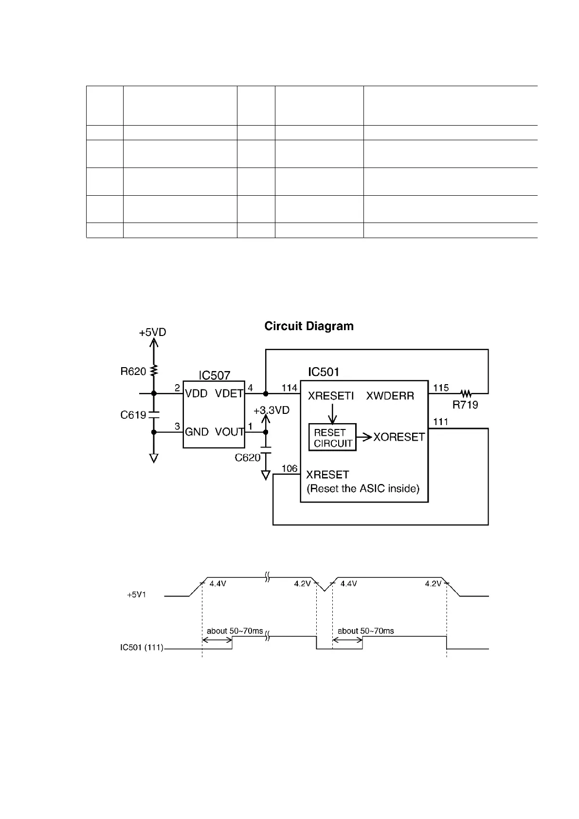
7.3.6. RESET CIRCUIT (WATCH DOG TIMER)
The output signal (reset) from pin 4 of the voltage detect IC (IC507) is input to the ASIC (IC501)
114 and 106 pins.
1. During a momentary power interruption, a positive reset pulse of
50~70 msec is generated and the system is reset completely.
2. The watch dog timer, built-in the ASIC (IC501), is initialized by the
CPU about every 1.5 ms.
When a watch dog error occurs, pin 115 of the ASIC (IC501)
157
 Loading...