• The
SD Memory Card must be inserted in the SD Memory Card slot of the DMPR card before startup.
Note
• For details about connecting peripherals, refer to
"2.9.1 Connection of Peripherals".
• For details about System Initialise Switch, refer to "2.11.1 Starting the PBX".
• For details about Reset Button, refer to "4.1.4 Using the Reset Button".
• When connecting the RJ11 or RJ45 connector, attach the included ferrite core. Refer to
"2.2.8 Attaching a Ferrite Core".
• Portions of this product contains software of Datalight, Inc. Copyright 1993–2000 Datalight,Inc., All
Rights Reserved.
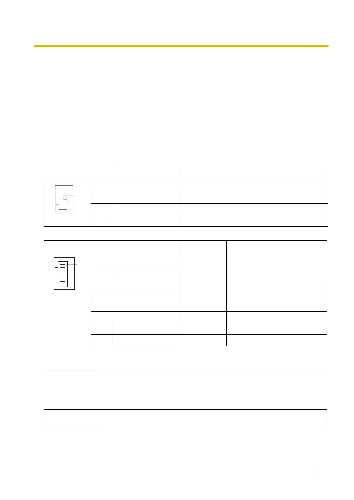
Pin Assignments
RJ11 Connector
No. Signal Name Function
1 D2A Data port 1 (Low)
2 D2B Data port 2 (Low)
3 D1B Data port 2 (High)
4 D1A Data port 1 (High)
RJ45 Connector
No. Signal Name Level [V] Function
1 MOH1 Nonpolar Music on Hold Jack: Port 1
2 MOH1 Nonpolar Music on Hold Jack: Port 1
3 PAG2 Nonpolar External Paging Jack: Port 2
4 PAG1 Nonpolar External Paging Jack: Port 1
5 PAG1 Nonpolar External Paging Jack: Port 1
6 PAG2 Nonpolar External Paging Jack: Port 2
7 MOH2 Nonpolar Music on Hold Jack: Port 2
8 MOH2 Nonpolar Music on Hold Jack: Port 2
LED Indications
Indication Colour Description
BATT ALARM Red Battery alarm indication
• OFF: Normal
ON: Alarm
SD ACCESS Green SD memory card status
• ON: Accessing
Installation Manual 59
2.3.1 DMPR Card
 Loading...