Chapter 2 Getting Started — Connecting
ENGLISH - 35
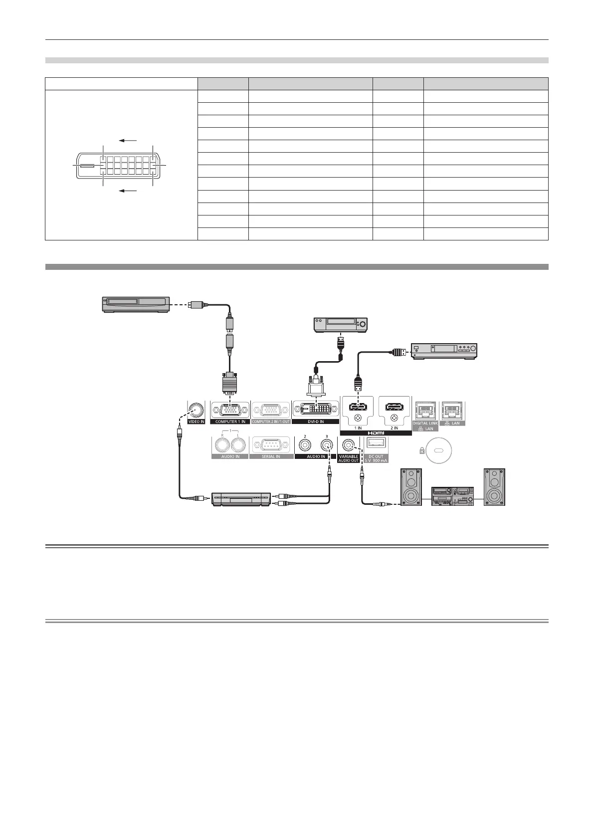
<DVI-D IN> terminal pin assignments and signal names
Outside view Pin No. Signal name Pin No. Signal name
(17)(24)
(16)
(9)
(1)(8)
(1) T.M.D.S data 2
-
(13) ―
(2) T.M.D.S data 2+ (14) +5 V
(3) T.M.D.S data 2/4 shield (15) GND
(4) ― (16) Hot plug detection
(5) ― (17) T.M.D.S data 0
-
(6) DDC clock (18) T.M.D.S data 0+
(7) DDC data (19) T.M.D.S data 0/5 shield
(8) ― (20) ―
(9) T.M.D.S data 1
-
(21) ―
(10) T.M.D.S data 1+ (22) T.M.D.S clock shield
(11) T.M.D.S data 1/3 shield (23) T.M.D.S clock+
(12) ― (24) T.M.D.S clock
-
Connecting example: AV equipment
Blu-ray disc player
VCR (with built-in TBC)
DVD player with HDMI terminal (HDCP)
Audio device
DVD player
S-video cable (commercially
available)
D-SUB - S Video conversion cable
(Optional (Model No.: ET-ADSV))
Attention
f Be sure to use one of the following when connecting a VCR.
g Use a VCR with built-in time base corrector (TBC).
g Use a time base corrector (TBC) between the projector and the VCR.
f The image may be disrupted when nonstandard burst signal is connected. In such a case, connect the time base corrector (TBC) between
the projector and the external devices.
Note
f Switching of the setting in the [DISPLAY OPTION] menu → [DVI-D IN] → [EDID SELECT] may be required depending on the connected
external device when DVI-D is input.
f The <DVI-D IN> terminal can be connected with the HDMI and DVI-D compatible devices. However, some external devices may not be able
to project images properly, such as the image not displaying.
f For the HDMI cable, use an HDMI High Speed cable that conforms to the HDMI standards. If a cable that does not conform to the HDMI
standards is used, images may be interrupted or may not be projected.
f The <HDMI 1 IN>/<HDMI 2 IN> terminals can be connected to an external device with the DVI-D terminal by using an HDMI/DVI conversion
cable. However, this may not function properly for some external devices, and image may not be projected.
f The projector does not support VIERA Link (HDMI).
f When Y/C signal is input to the <COMPUTER 1 IN> terminal using the optional D-SUB - S Video conversion cable (Model No.: ET-ADSV), it
is necessary to switch the setting with the [DISPLAY OPTION] menu → [COMPUTER IN/OUT] → [INPUT SETTING].
f When RGB signal or YC
B
C
R
/YP
B
P
R
signal input to the <COMPUTER 1 IN> terminal is output from the <COMPUTER 2 IN/1 OUT> terminal,
it is necessary to switch the setting with the [DISPLAY OPTION] menu → [COMPUTER IN/OUT] → [COMPUTER2 SELECT].

 Loading...