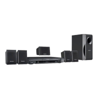
Do you have a question about the Panasonic SA-PT170PH and is the answer not in the manual?
| Brand | Panasonic |
|---|---|
| Model | SA-PT170PH |
| Category | Home Theater System |
| Language | English |
Essential guidelines for safe handling, maintenance, and general operation.
Procedures for cold and hot checks to prevent electrical shock hazards.
Instructions on setting the voltage selector before operating the unit.
Guidelines for safely discharging capacitors and restoring power post-repair.
Explanation of the protection circuit's function and troubleshooting steps.
List of critical safety components requiring manufacturer-specified replacements.
Techniques to prevent damage to sensitive components from static electricity.
Warnings and guidelines for safely handling the laser diode pickup unit.
Information on lead-free solder usage and legal restrictions for service.
Cautions for handling the optical pickup unit and grounding for ESD prevention.
Details on the service manual's content and ordering procedures for parts.
Technical details on amplifier output, tuner frequency range, and terminals.
Information on input/output terminals, playable disc formats, and video systems.
Guide to button functions and operations of the remote control unit.
Identification and function of buttons and indicators on the main unit.
Instructions for linked operations between the unit and a VIERA TV via HDMI.
Guidelines for connecting and playing media from USB devices.
Instructions for connecting external music devices to the unit.
Diagrams and instructions for connecting speakers to the main unit.
Details on supported disc types, formats, and playability restrictions.
Information on supported file formats for WMA, MP3, JPEG, MPEG4, and DivX.
Overview of service modes accessible via button combinations for checking.
Details on service modes, including button combinations and display information.
Error code tables for mechanism diagnostics to identify faults.
Function to prevent disc ejection and operation during sales demonstrations.
Process flow and instructions for updating the unit's firmware.
Guidance for diagnosing and resolving F61/F76 errors related to power supply.
Common problems and checking points for the DVD traverse unit.
Steps for diagnosing issues with HDMI video and audio output signals.
List of specific tools and equipment required for service procedures.
Visual guide showing the sequence of component disassembly.
Diagrams illustrating the placement of major components and PCBs within the unit.
Step-by-step instructions for removing the top cabinet.
Instructions for removing the rear panel of the unit.
Procedure for removing the DVD mechanism unit.
Steps for removing the front panel assembly.
Procedure for disassembling the panel and power button PCB.
Steps for removing the MPort/USB PCB.
Procedure for removing the microphone PCB.
Steps for removing the DVD lid.
Procedure for removing the AC inlet PCB.
Steps for removing the main PCB.
Procedure for removing the analog amplifier PCB.
Steps for replacing the 2CH BTL Power Amplifier IC.
Steps for replacing the 2CH BTL Power Amplifier IC.
Steps for replacing the 2CH BTL Power Amplifier IC.
Procedure for disassembling the SMPS and voltage selector PCBs.
Steps for replacing the switching regulator IC.
Steps for replacing the regulator diode.
Procedure for disassembling the DVD module PCB.
Instructions for assembling and disassembling the traverse unit.
Steps for accessing and performing checks on the main PCB.
Procedures for accessing and servicing the analog amplifier PCB.
Steps for accessing and performing checks on SMPS and AC inlet PCBs.
Procedures for accessing and performing checks on the DVD module PCB.
Tables showing reference voltage values for various ICs and pins on the DVD module.
Tables listing reference voltage values for ICs on the main PCB during different modes.
Reference voltage values for ICs on the panel PCB.
Reference voltage values for ICs and transistors on the analog amplifier PCB.
Reference voltage values for ICs and components on the SMPS PCB.
Reference voltage values for ICs on the microphone PCB.
Visual representations of expected waveforms at various ICs for diagnostic reference.
Visual identification of common ICs, transistors, and diodes used in the unit.
High-level overview of the unit's major functional blocks and interconnections.
Detailed block diagram illustrating the system control logic and component interaction.
Block diagram showing the DVD servo system, including pickup unit and motor drivers.
Block diagram detailing the audio signal processing path from input to output.
Block diagram illustrating the HDMI interface signal flow and processing.
Block diagram showing the video signal path, including input, processing, and output.
Detailed block diagram of the audio signal processing and amplification stages.
Block diagram of the analog amplifier section, showing power stages and controls.
Block diagram of the power supply unit, detailing voltage regulation and distribution.
Diagram illustrating the interconnection of PCBs and components via wiring harnesses.
Explanations of units, symbols, and important safety notices for schematic interpretation.
Detailed circuit diagrams for the DVD module, covering servo, audio, and HDMI functions.
Circuit diagrams for the main PCB, showing system control and tuner pack connections.
Circuit diagrams for the panel, including buttons, FL display, and remote sensor.
Circuit diagrams for the MPort/USB interface and power button assembly.
Detailed circuit diagrams for the analog amplifier section, including power ICs.
Circuit diagrams for the switching mode power supply unit.
Circuit diagrams for the AC power input and voltage selection circuitry.
Circuit diagrams for the microphone input and audio processing section.
Physical layout diagrams for the DVD module PCB (Side A and Side B).
Physical layout diagram for the main PCB, showing component placement.
Layout diagrams for the panel, MPort/USB, power button, and AC inlet PCBs.
Physical layout diagram for the analog amplifier PCB.
Physical layout diagram for the switching mode power supply PCB.
Layout diagrams for the microphone and voltage selector PCBs.
Pin assignments and functions for the main microprocessor IC.
Pin assignments and functions for the FL display driver IC.
Illustrated breakdown of the unit with a list of mechanical replacement parts.
Detailed list of mechanical parts with part numbers and descriptions.
Comprehensive list of electrical components with part numbers for replacement.
 Loading...