47
9 Disassembly and Assembly Instructions
“ATTENTION SERVICER”
Be careful when disassembling and servicing.
Some chassis components may have sharp edges.
Special Note:
1. This section describes the disassembly procedures for all the major printed circuit boards and main components.
2. Before the disassembly process was carried out, do take special note that all safety precautions are to be carried
out.
(Ensure that no AC power supply is connected during disassembling.)
3. For assembly after operation checks or replacement, reverse the respective procedures.
Special reassembly procedures are described only when required.
4. Do take note of the locators on each printed circuit board during reassembling procedures.
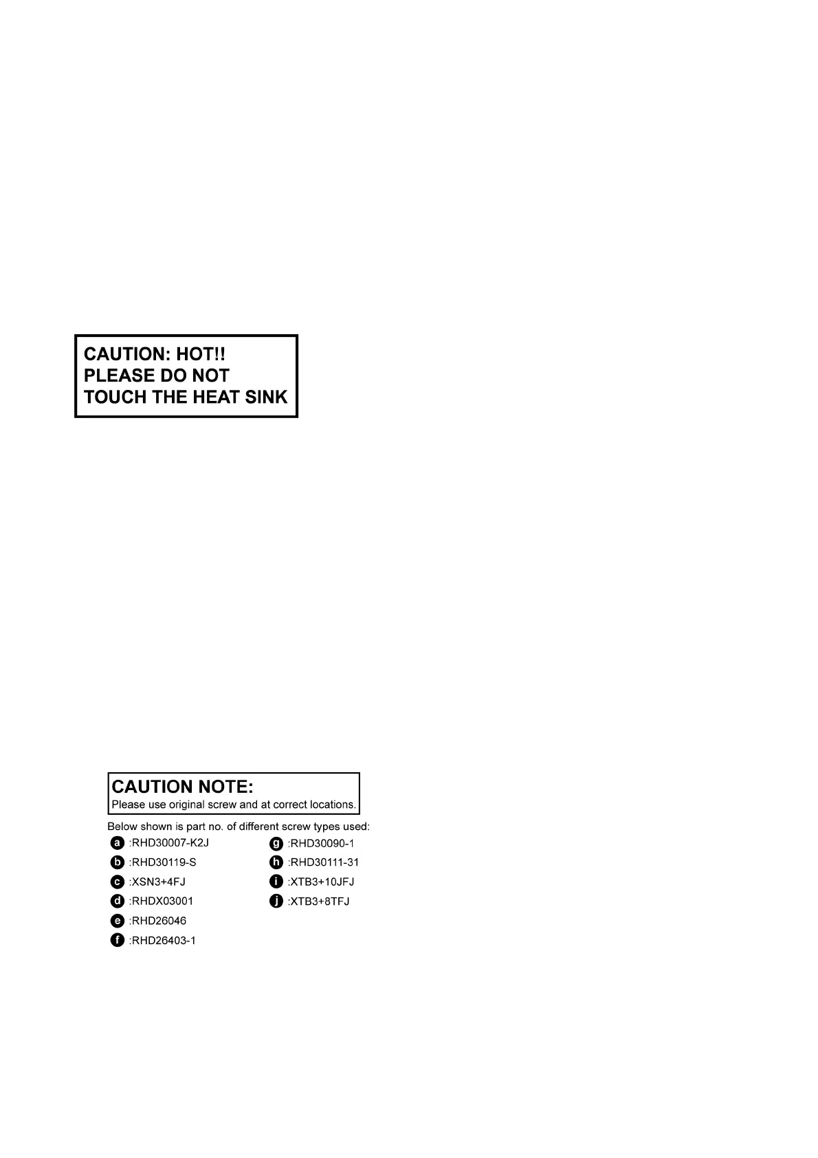
5. The Switch Regulator IC may have high temperature after prolonged use.
6. Use caution when removing the top cabinet and avoid touching heat sinks located in the unit.
7. Select items from the following index when checks or replacement are required.
• Disassembly of Top Cabinet
• Disassembly of Rear Panel
• Disassembly of DVD Mechanism Unit (DLS6)
• Disassembly of Front Panel Assembly
• Disassembly of Panel, Power Button P.C.B.
• Disassembly of MPort / USB P.C.B.
• Disassembly of Mic P.C.B.
• Disassembly of DVD Lid
• Disassembly of AC Inlet P.C.B.
• Disassembly of Main P.C.B.
• Disassembly of Analog Amp P.C.B.
• Replacement of 2CH BTL Power Amplifier IC (IC5100)
• Replacement of 2CH BTL Power Amplifier IC (IC5200)
• Replacement of 2CH BTL Power Amplifier IC (IC5300)
• Disassembly of SMPS P.C.B & Voltage Selector P.C.B.
• Replacement of Switching Regulator IC (IC5701)
• Replacement of Regulator Diode (D5802)
• Disassembly of DVD Module P.C.B.
• Assembling and Disassembling of Traverse Unit