97
16 Schematic Diagram Notes
• This schematic diagram may be modified at any time
with the development of new technology.
Notes:
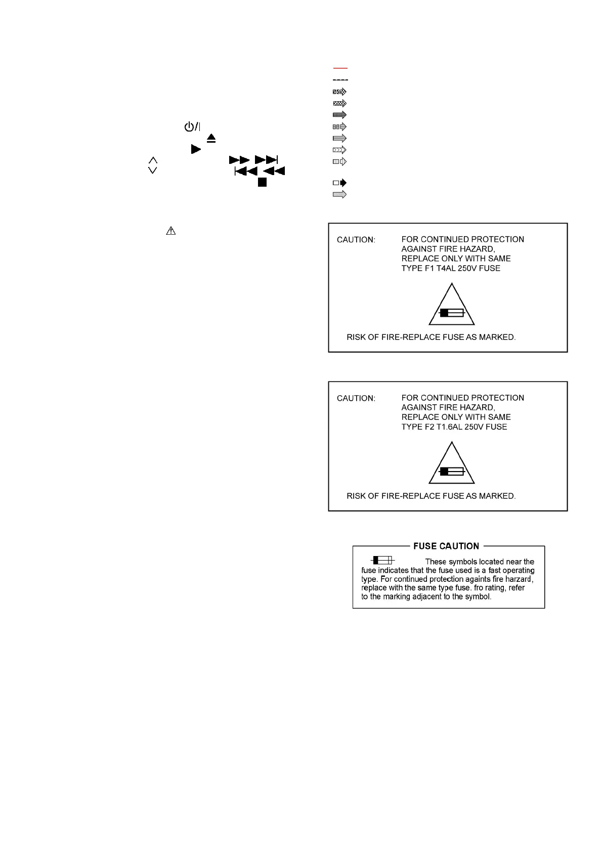
• Important safety notice:
Components identified by mark have special characteris-
tics important for safety.
Furthermore, special parts which have purposes of fire-retar-
dant (resistors), high quality sound (capacitors), low-noise
(resistors), etc are used.
When replacing any of components, be sure to use only
manufacturer’s specified parts shown in the parts list.
• In case of AC rated voltage Capacitors, the part no. and val-
ues will be indicated in the Schematic Diagram.
AC rated voltage capacitors:
C5700, C5701, C5702, C5706, C5707, C5708
• Resistor
Unit of resistance is OHM [Ω] (K=1,000, M=1,000,000).
• Capacitor
Unit of capacitance is µF, unless otherwise noted. F=Farads,
pF=pico-Farad.
• Coil
Unit of inductance is H, unless otherwise noted.
•
*
Ref is for indication only.
• Voltage and signal line
S5701: Vol ADJ Switch.
S6801:
Power switch ( ).
S6807:
Open/Close switch ( ).
S6901:
Memory switch ( ).
S6902:
Tune /Forward switch ( / ).
S6903:
Tune /Backward switch ( / )
S6904:
-Tune mode/—FM mode switch ( ).
S6907: Selector switch.
VR6901: Volume jog.
: +B signal line
: -B signal line
: Audio output signal line
: Video output signal line
: Audio & Video output signal line
: CD/DVD Audio input signal line
: CD/DVD Video input signal line
: CD/DVD Audio & Video input signal line
: Optical/TV/Music Port/AUX Audio input
signal line
: FM signal Line
: USB signal line