67
10 Service Position
10.1. Checking & Servicing Main
P. C. B .
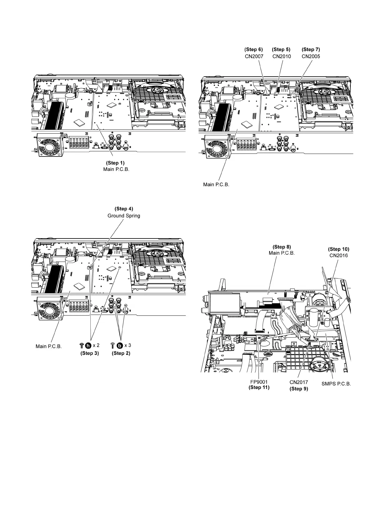
Step 1 Remove the top cabinet to service Main P.C.B.
10.2. Checking & Analog Amp P.C.B.
Step 1 Remove the top cabinet.
Step 2 Remove 3 screws at the rear panel.
Step 3 Remove 2 screws on Main P.C.B.
Step 4 Remove 1 ground spring on Main P.C.B.
Caution: Keep the 1 ground spring in safe place. Avoid
denting it. Place it back during assembling.
Step 5 Detach 7P cable at the connector (CN2010) on Main
P. C .B .
Step 6 Detach 19P FFC at the connector (CN2007) on SMPS
P. C .B .
Step 7 Detach 10P cable at the connector (CN2005) on Main
P. C .B .
Step 8 Detach Main P.C.B. from the rear panel and position it
according to the diagram shown.
Step 9 Detach 8P cable at the connector (CN2017) on SMPS
P. C .B .
Step 10 Detach 14P cable at the connector (CN2016) on
SMPS P.C.B.
Step 11 Detach 5P cable at the connector (FP9001) on DVD
Module P.C.B.