19 Schematic Diagram Notes
·
This schematic diagram may be modified at any time
with the development of new technology.
Notes:
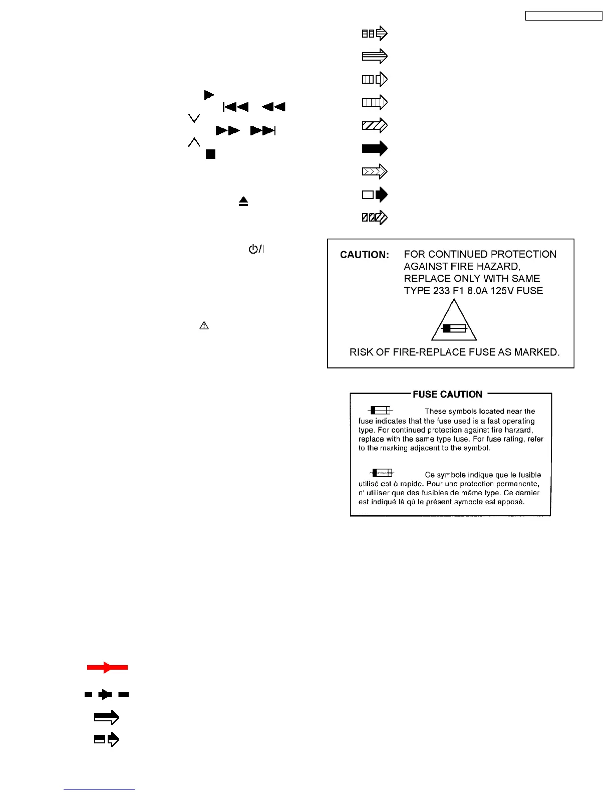
S6801: Play switch (
/ MEMORY).
S6802: Backward switch (
/ /
TUNING
).
S6803: Forward switch (
/ /
TUNING
).
S6804: Stop switch (
/ -TUNE MODE/—
FM MODE).
S6805: DISC EXC switch (—EXCHANGE).
S6806: DISC SKIP switch. (—SKIP)
S6808: Open / close switch (
OPEN /
CLOSE).
S6809: (Volume) Up switch.
S6810: (Volume) Down switch.
S6900: Power switch (POWE R
).
S6902-S6906: DISC 1- DISC 5 switch (5 DISC
SELECTOR)
S6907: SELECTOR switch.
S9001: LOAD switch.
·
Important safety notice:
Components identified by
mark have special
characteristics important for safety.
Furthe rmore, special parts which have purposes of fire-
retardant (resistors), high-quality sound (capacitors), low-
noise (resistors), etc. are used.
When replacing any of components, be sure to use only
manufacturer´s specified parts shown in the parts list.
·
In case of AC rated voltage Capacitor, the part no. and
values will be indicated in the Schematic Diagram.
AC rated voltage capacitor:
C5700, C5701,C5703, C5704, C5705
·
Resistor
Unit of resistance is OHM [Ω] (K=1,000, M=1,000,000).
·
Capacitor
Unit of capacitance is µF, unless otherwise noted. F=Fara d,
pF=Pico-Farad
·
Coil
Unit of inductance is H, unless otherwise noted.
·
Voltage and signal line
: +B signal line
: -B signal line
: DVD RF signal line
: Motor Drive signal line
: DVD Audio signal line
: DVD Video signal line
: CD Head signal line
: DVD Head signal line
: Main signal line
: Tracking Error signal line
: Focus Error signal line
: FM, XM signal line
: AUX, Music Port, Ipod signal line
99
SA-PT750P / SA-PT750PC